


New Shop Wiring
the_analyst
14 years ago
Sort by:Oldest
Comments (9)
Related Stories
SHOP HOUZZShop Houzz: Down to the Wire
Versatile wire furniture and accents mesh well with all styles, from traditional to modern
Full Story0
LIGHTING10 Ways With Wall Lights That Don’t Need to Be Wired In
Learn how to add illumination to your home without carving into the walls
Full Story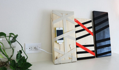
DIY PROJECTSHide All Those Wires in a DIY Charging Station
Keep your gadgets handy and charged with a flexible storage board you can design yourself
Full Story
SHOP HOUZZShop Houzz: Farmhouse-Style Storage
Get organized with well-worn wire and wood storage pieces that capture a farmhouse spirit
Full Story0
SHOP HOUZZShop Houzz: Go Go Gadgets
Shop these new and improved tech gadgets, from charging stations to speakers
Full Story0
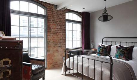
SHOP HOUZZShop Houzz: Industrial Style for the Bedroom and Bath
Give your bed and bath a crisp edge with industrial-inspired furnishings
Full Story0
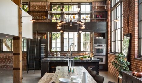
SHOP HOUZZShop Houzz: Industrial Style for the Kitchen and Dining Room
The perfect recipe for assembling a warm and welcoming industrial kitchen and dining room
Full Story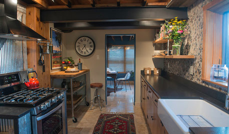
SHOP HOUZZShop Houzz: 3 Ways to Warm Up an Industrial Kitchen
Warm woods, global textiles and lush greenery turn industrial from cold to cozy
Full Story0
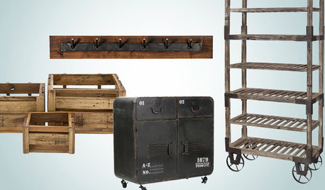
SHOP HOUZZShop Houzz: Our Favorite Rustic Industrial Storage
Get organized with stylishly rugged bins, hooks, shelving and racks
Full Story0
SHOP HOUZZA Rustic Farmhouse Kitchen
Rough-hewn furnishings and accessories for a charming space
Full Story
petey_racer
the_analystOriginal Author
Related Professionals
Auburn General Contractors · Buena Park General Contractors · Medford General Contractors · Rocky Point General Contractors · Rolling Hills Estates General Contractors · West Lafayette General Contractors · Elmwood Park Solar Energy Systems · Jollyville Home Automation & Home Media · Kissimmee Home Automation & Home Media · Oak Hill Home Automation & Home Media · Pittsburgh Home Automation & Home Media · San Fernando Home Automation & Home Media · Surfside Home Automation & Home Media · Waukegan Home Automation & Home Media · West Chester Home Automation & Home Mediajoed
brickeyee
the_analystOriginal Author
normel
the_analystOriginal Author
billhart
hrajotte