


It's not a TV antenna wire... what IS it?
central_valley
11 years ago
Sort by:Oldest
Comments (8)
Related Stories
ACCESSORIESHow to Hide Those Messy Wires
Untangle Yourself From Ugly Electrical Cords With a Few Tricks and Accessories
Full Story
MORE ROOMSHome Tech: Getting Rid of Wires Without Sacrificing Sound
Wireless home technology still isn't perfect, but new products are giving audiophiles choices
Full Story
HOME TECHNew Strategies for Hiding the TV
Its easy to be discreet when you've got cabinets, panels and high-tech TV hiders like these
Full Story
MEDIA ROOMSHome Tech: Making a Media Console Work
How to manage your TV and component's wires, ventilation and communication with the remote control
Full Story
MORE ROOMSMedia Wall Hides the Television in Plain Sight
Award-winning media wall makes TV screen part of the design, hides the wires away
Full Story
HOME TECHGo Ahead: Embrace Your Home Technology
It's time to make peace with the gadgets, wires and TV screens that serve us so well
Full Story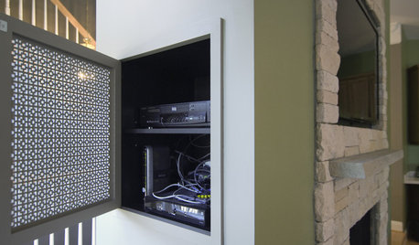
DECORATING GUIDESHow to Hide Your TV Cables
Make your TV room clutter-free by hiding your electronics in the wall
Full Story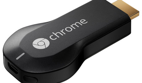
HOME TECHNow Playing in Homes Everywhere: TV, the App
It's easier than ever to beam streaming content from mobile devices to your TV screen
Full Story
BEFORE AND AFTERSHouzz TV: See Recycled Walls and Cool Cassette Art in a Woodsy DIY Home
Walnut countertops join hardwood floors and pieces made from leftover framing in a bright Spanish colonial
Full Story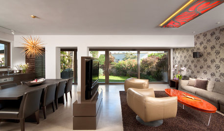
MORE ROOMSWhere to Put the TV When the Wall Won't Work
See the 3 Things You'll Need to Float Your TV Away From the Wall
Full StoryMore Discussions

tjdabomb
alan_s_thefirst
Related Professionals
Lake Nona Electricians · Aurora General Contractors · Aurora General Contractors · Chatsworth General Contractors · Cumberland General Contractors · DeRidder General Contractors · Elyria General Contractors · Jacksonville General Contractors · Leon Valley General Contractors · Syosset General Contractors · Saratoga Solar Energy Systems · Fort Lauderdale Home Automation & Home Media · South Lake Tahoe Home Automation & Home Media · Town 'n' Country Home Automation & Home Media · Annandale Home Automation & Home MediaRon Natalie
brickeyee
yosemitebill
brickeyee
bus_driver
yosemitebill