


Wiring a timer for lights - 3 wires?
whaas_5a
11 years ago
Sort by:Oldest
Comments (15)
Related Stories

LIGHTING10 Ways With Wall Lights That Don’t Need to Be Wired In
Learn how to add illumination to your home without carving into the walls
Full Story
LIGHTINGThe Pros and Cons of Recessed Lighting
A lighting designer shares three things recessed lights do well and three things to watch out for
Full Story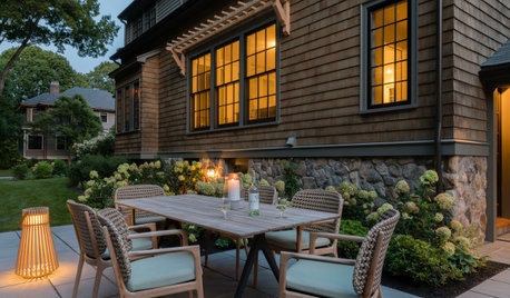
LANDSCAPE DESIGN3 Ways to Light the Garden With Less
Use less energy and lower your electricity bill with these landscape lighting options
Full Story
LIGHTING3 Ways LED Lights Are Better Than Ever
See how improved technology has made LED lightbulbs smaller, brighter and more colorful
Full Story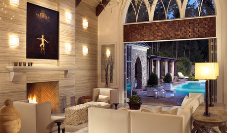
MORE ROOMSHome Tech: Getting Rid of Wires Without Sacrificing Sound
Wireless home technology still isn't perfect, but new products are giving audiophiles choices
Full Story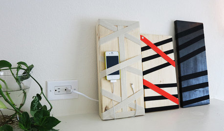
DIY PROJECTSHide All Those Wires in a DIY Charging Station
Keep your gadgets handy and charged with a flexible storage board you can design yourself
Full Story
LANDSCAPE DESIGNSee 10 Elegant Ways With Stone and Wire
The gabion, a former utilitarian landscape feature, gets star treatment in modern-day landscapes
Full Story
LIGHTING3 Reasons to Hire a Lighting Designer
Learn why adding a lighting expert to your home remodeling team is a bright idea
Full Story
KITCHEN DESIGNKitchen Remodel Costs: 3 Budgets, 3 Kitchens
What you can expect from a kitchen remodel with a budget from $20,000 to $100,000
Full Story
WHITE KITCHENSNew This Week: 3 White Kitchens, 3 Different Styles
A few key accents can make one all-white kitchen look and feel completely distinct from another
Full Story
Ron Natalie
whaas_5aOriginal Author
Related Professionals
Banning General Contractors · Broadview Heights General Contractors · Canandaigua General Contractors · Goldenrod General Contractors · Homewood General Contractors · Hutchinson General Contractors · Jackson General Contractors · Maple Heights General Contractors · Rosemead General Contractors · Warrenville General Contractors · Travilah General Contractors · El Mirage Solar Energy Systems · Phoenix Solar Energy Systems · Reedley Solar Energy Systems · Half Moon Bay Home Automation & Home Mediawhaas_5aOriginal Author
whaas_5aOriginal Author
brickeyee
yosemitebill
whaas_5aOriginal Author
yosemitebill
whaas_5aOriginal Author
yosemitebill
brickeyee
whaas_5aOriginal Author
yosemitebill
whaas_5aOriginal Author
yosemitebill