


Generac Generator "Wireless Status" protocol?
I have a Generac Guardian 20 kW generator.
I noticed there is a 100-300$ wireless monitor system. I am pretty handy with micro controllers and doing this myself. I am curious, if anyone knows how the wireless receiver (the part on the generator) communicates with the main controller?
From the install instructions found here
http://www.powerequipmentdirect.com/manuals/nexusadvwirelessmanual.pdf
It looks as if there is Power/Ground and 1 Data wire. So, possibly just Serial (UART)?
Thanks
Comments (36)

Ron Natalie
11 years agoDon't know about the 20K but on my 80k, it's an RS-422 serial interface for the remote control unit.
aberson
10 years agoDid you have any luck with this? I came across the same install manual and presumed power, ground, data. But the wireless remote has 2-way communication, so it might be something more complicated than a regular serial port.
The install notes for the MobileLink (one-way cellular based monitoring) are found here: http://www.generac.com/Manuals/0K2289_MobileLinkUserManual.pdf
They mention a 6-pin harness on the mobilelink side (only appears that 3 or 4 wires are populated). It seems to use the same 8-pin accessory connector, and they also mention that for this unit the power lines get hooked directly to the battery - maybe it uses more power than the accessory port can handle.
The simpler 3-light wireless module seems to tap into the wiring harness for the status LED's on the top of the generator, rather than use the serial port: http://www.electricgeneratorsdirect.com/manuals/5928_man.pdf
Related Professionals
Country Club Hills General Contractors · Ewing General Contractors · Groton General Contractors · Jackson General Contractors · Mankato General Contractors · Medway General Contractors · Signal Hill General Contractors · Forest Park Solar Energy Systems · Gardena Solar Energy Systems · Danville Home Automation & Home Media · Delray Beach Home Automation & Home Media · Glendale Heights Home Automation & Home Media · Leesburg Home Automation & Home Media · Pittsburgh Home Automation & Home Media · Robbinsdale Home Automation & Home Mediabantaj
10 years agoI'm very interested in this too. Just got the 14kw Generac model and it came with a free 12 month mobilelink subscription but curious how I can leverage an arduino or other microcontroller to monitor the 8 pin accessory output without the subscription fees that come with mobilelink.
Ron Natalie
10 years agoFirst off, you only need the subscription if you are using the MOBILELINK (cellular device). If you just want local control you can plug other devices into that port instead. Generac makes a wireless LOCAL link (so you can watch it from inside the house somewhere) that doesn't require a subscription.
The interface is RS-422 I'm fairly sure. You can get adapters to connect it to various devices. I've not bothered trying to hack mine yet.
bantaj
10 years agoIn response to tonnatalie, yes, I agree the subscription is required only if I want to use the mobilelink service but what I envisioned was connecting a microcontroller (such as an arduino) and have it monitor for the same errors/alerts/messages that the mobile link device transmits.
The benefit here is that one could then use other protocols such as wi-fi to transmit the data to a computer inside or, better yet, a server offsite where it can be logged, accessed remotely or sent via text message when updates received.
I realize that's basically what the mobilelink does (except they use cell transmissions for the data) which has it's pros & cons in my opinion:
+ Good because it's easier to set up and is not dependent on wifi being live like my home-brew solution (the wi-fi issue could be addressed a couple different ways I'm sure)
- Bad because it costs $5-10/month in extra fees + the equipment for anyone who doesn't have the $250 unit already.
I like the idea of having my own solution in place plus I enjoy trying to figure this stuff out (see my blog for info on a sump pit water level monitor I built using similar microcontroller in the link below)
Back to the generator monitor question at hand...
I've had my Generac 14kw fr a week now and have seen the following status codes come through on the mobilelink during setup and initial runs.I assume there are more fault codes to consider but would be interested in hearing if anyone figures out how these are sent/can be read from the accessory port.
Codes seen so far:
1. Your generator is ready to run.
2. Your generator is running in exercise mode.
3. The generator has been set to the OFF position and will not start automatically in response to an outage.
4. Your generator is running due to utility power being lost.
5. The generator has been set to the OFF position and will not start automatically in response to an outage.
6. The generator has been set to manual operation and is running.
7. The battery charge level is too low. Please inspect/replace the battery or call your service/maintenance provider.
8. AC power to your generator's battery charger has been lost. Please check the circuit or contact your service/maintenance provider for assistance.
9. Your unit has blown the fuse or the fuse is missing (E2400). Please reference your owner's manual to replace the fuse or contact your service/maintenance provider.Here is a link that might be useful: my sump-pit water level monitor
Ron Natalie
10 years agoYou don't even need an Ardino. You can purchase an RS-422 to RS-232 converter and then something like the GlobalCache serial to wifi interface. I've used that to talk to other devices. You just open a socket to port 4998 (if I recall properly) and send and receive.
zeke7237
10 years agoDid you ever get anywhere with this? I had a 10KW with nexus controller installed last fall, I've got a couple of RS485/422 converters from previous projects, but I've not found any pinout information on the connector used for the Generac remotes ..
Ron Natalie
10 years agoLooks like the pseudo-standard DB-9 on mine. The bigger issue is the protocol on the wire. I thought I saw the connections in one of the docs but they're down at the site right now.
Nomadlogo
10 years agoI would be very interested in this project, as I assumed many others would be. The downside to the mobile link has already been listed, it is a pay per month service, cellular versus local wireless and you would have to purchase their expensive hardware. Add to that you do not have control of the logging or data (it is on their website) and you have all the reasons you need to create an arduino or similar solution.
Here is what I have been able to find so far, this is a 3 wire (with ground) serial connection and is very likely using modbus. If it is in fact Modbus, one should be able to slave a laptop to a serial link with the mobilelink on it, and sniff the activity on the wire to see what is data / commands are available. In looking elsewhere on the web, it seems as if OMNIMETRIX also makes a solution for generac, i would guess mobilelink was generac direct answer to it. That solution can monitor several activities that are listed here in the generac link
http://www.omnimetrix.net/Products/GeneratorMonitoring
I seenow indication that omnimetrix is a partner of generac nor that generac opens the controller with an API, etc., so my guess is that what they can see is readily available from the controller's serial port.
This info should get someone started... I do not have enough experience "yet" to build any of these arduino, pi, intel controlellrs myself, but I would be willing to help where i could. If there is enough like minded people on this, maybe we can start a project website.
bantaj
10 years agoI have not had a chance to make any progress on this due to the weather but glad to see more people on this thread. I plan on taking a closer look at the hardware interface once the weather improves a bit here in Chicago.
I haven't played with wireless interfaces before but reading up on serial communications over XBee or similar hardware to communicate with a remote PC a inside the house (a hundred or so feet away).
Thanks for the link to Omnimetrix...reading up on that now.
mopar99
10 years agoI'm also interested in this. I have a 20k with the wireless monitor unit posted in the first posting. I've been looking into this for a while and stubble upon this thread which has provide some insight. I know that the wireless monitoring unit is a freescale design version of the xbee design.
adamgoldberg
10 years agoThe Nexus/Evolution control panel (like on my 2013 model 20kw Guardian) has a 8-pin connector on the bottom, which includes a modbus interface. See the OMNIMETRIX installation instructions (link below).
I suspect that a careful viewing of the picture in the installation instructions will yield knowledge of which pins are used for the modbus, and then some sort of modbus interface to a PC or whatever would yield a system where you can attempt to determine exactly how to get exactly what information out of the generator.
In speaking with OMNIMETRIX, it seems that the Nexus/Evolution panel is very similar to the modern commercial Generac systems...
I don't know if one would be able to extract modbus register information from Generac or not. It's probably worth a TRY. Might be easier to extract that data from Generac by asking about the commercial systems.
If anyone wants to try to collaborate on this, please let me know.
In any case, the OMNIMETRIX system is around the same cost as the Generac monitoring system, but monitors a whole lot more things.
http://info.omnimetrix.net/installation_Generac_NEXUS_Panel.pdf
chrisn_NH
9 years agoAdam - I'm interested in collaborating with you. I've purchased the MobileLink and will use the first year of free cell service to figure out the Modbus. Intention is to tap off the serial to a RasberryPi or something and go wireless.
I'm waiting on the electrician to pull the house meter and get power to the unit but in the meantime, I'm installing the mobilelink. I've toned out the wiring harness and have the information for that here:
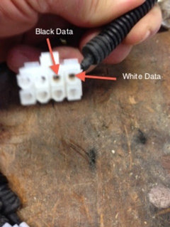
1. The harness has three ends: two terminal lugs for the +12V from the battery; one 6 pin connector that carries +12V, ground and two-pin serial to the MobileLink; One 8 pin connector that carries 2-wire serial from the generator controller board.
2. I've attached a picture of the 8 pin keyed connector from the controller board. If the top left pin is #1 counting clockwise, the serial interface is on pins 3 and 4 (black and white wires respectively).
3. The only odd thing is that on the 6 pin mobilelink connector, there is a wire that is molded into the connector that is not used (#1). I have tested for continuity between it and everything else and there is none. Kind of odd but all I can think of is they use that harness for other products/generators and simply don't need it on the Generac. Out of the 6 pins, there are 2 serial, 2 power, the unused and an empty one.
Next step is to install the MobileLink, get power to the generator and then I'll measure signal levels on the two serial lines as the generator is talking to the MobileLink with an oscilloscope to make sure I know what "RS" standard interface this is before I risk hooking up a unix box and attempting to read data from it. If you have the capability and are able to do that using this info; please do and forward me a stream capture.
Have you made any progress?
Chris
chrisn_NH
9 years agoBy working on the MobileLink device and taking a look inside, I've discovered they are using a SIPEX SP3232EEN RS-232 transceiver so, given there is a blk and white data port and we know the connection is two-way, they are using a simple 3-wire RS-232 connection. The MobileLink is using a +-5V signaling scheme but the 3232 can handle from 3.3V to 15v. The white wire in my picture is R1 IN to the MobileLink so this is T1 OUT from the Generac. The black wire is T1 OUT on the Mobilelink so that's R1 IN on the generac. Now its a matter of figuring out the baud and seeing just how proprietary their modbus is. It should be possible to simply connect a Raspberry Pi to the data lines while the MobileLink is first activated and log all of the comms between the Generac and the MobileLink.
chrisn_NH
9 years agoThe unused pin on the 6 pin connector coming out of the Mobilelink turns our to simply be the shielding on the wire, although this is not terminated to system ground on the generator, it may be a system ground on the cell transceiver put there to reduce noise on the line going into the MobileLink.
I am also thinking they cheated a bit and aren't even using a 3-wire signaling scheme but only a two wire. I think this because if one looks at what comes out of the mobilelink T1 line reference to ground, the signal levels are about
-15V to -5V which doesn't make sense. Hence I'm pretty sure they're using this in differential mode with T1 referenced to R1 and vice versa. This gives signaling levels of 5 to -5 V which of course is just TTL.Next step is to insert a 3.3 to 5V level converter so the raspberrypi can get to snooping.....
vincefleming
9 years agoThis is awesome! I've had my 20Kva Guardian since 3 days before Sandy - it was a lifesaver! I have always wanted to do something like this, down to going out and buying a raspberripi and everything, but back then, there was no remote accessory I could just hack, so I never really got far with it.
Chrisn_NH - how did you make out with hacking the interface? Did you ever get it to work? If so, could you please post about how you got it to work?
Thanks!
fb55
9 years agochrisn_NH, did you get to the next step...snooping?
Has anyone made further progress with the actual control protocol?
mopar99
9 years agonice work Chris...Now i'm gonna have to go check my unit to see if the wiring is the same for the wireless unit that i have. been a while since i looked at it last.
bantaj
8 years agoChecking back into this thread as I had to take a break from this project before making any worthwhile progress. Looks like others have some great ideas and skills beyond mine to explore this further. Would love to read more about your project Chris if there's any advice you can pass on.
1lb6bc_a27r9f7ctio60
8 years agolast modified: 8 years agoI'm also very interested in this. MobileLink will not work in my country. I found a manual that might shred some light? IDK...http://soa.generac.com/manuals/0060720/0G5354
I own a Guardian 13kVA Evolution series. It has 2 accesory ports and 1 three pins connector.
EDIT: Some more info: http://www.chipkin.com/support/more-support/other-drivers/generac-support-knowledge-and-faq/ - http://www.chipkin.com/products/gateways/more-gateways/generac-gateways/ - http://www.pythiatech.com/pdf/PTECH_MS_MS0_RS24H.pdf - http://www.google.com/patents/US8224499 - http://aapower.com/pdfs/Remote%20annunciator.pdf
Oskar Atkinson
8 years agoHowdy .. glad I found this thread. Just got a 11KW gen, bought Mobilink and am %^^* that I did not read about the cell service requirement.
Anyways, if the protocol really is modbus - then I'll give it a try. I am using this: https://www.olimex.com/Products/OLinuXino/A20/A20-OLinuXino-MICRO/open-source-hardware
and
https://www.olimex.com/Products/Modules/Interface/MOD-RS485/open-source-hardware
to read status info from a Morningstar charge controller.
1lb6bc_a27r9f7ctio60
7 years agoHi Oskar,
Really great to see some movement here. I'm very interested in this. Please let me know how it went.
Oskar Atkinson
7 years agowell, might take a while. I got mobile link working with a Verizon range extender - now I need to sniff the protocol
1lb6bc_a27r9f7ctio60
7 years agoHi Oskar
It's great that you made it work!
Were you able to sniff the protocol?
spacey123765
7 years agolast modified: 7 years agoVery psyched about this. I just searched for an open source project to replace Mobile Link. The cost isn't worth it, especially seeing as our cellular service isn't great (but still isn't worth it for me). The A20-OLinuXino board (or whatever hardware is used) solution would be completey bad-ass!
Cannot wait to see your progress. I have a 2015 Generac 20kW running on propane. If at some point you'd like another alpha or beta tester, I'm in!
spacey123765
7 years agoNoooo! :) please update is if you ever get back around to this. Have you started a project on Github, to get other contributors?
- PRO
IT Pros of North Texas
7 years agoWe have had several inquires about this and will start work on developing a RaspberryPi solution... before we reinvent the wheel, does anyone have any real test data that we can take a look at before we start? Is it truly RS232? Please let me know.
jimpasquini
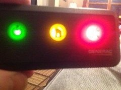
7 years agoI have Generac 22kw natural gas generator with the 3 light, wireless local monitor. I just changed the oil, the oil filter, air filter, and spark plugs as part of the annual maintenance but my wireless monitor on fridge is still flashing all 3 lights at once (green, yellow, and red). The generator itself is showing ready for operation and the status light on the generator is green. How do I reset the wireless monitor so it's back to showing just the green light with the open circle and lightening bolt icon? I think have tried about everything at the generator and every time I hold the button in on the monitor, it toggles through the 3 lights and then stays red (wrench and screwdriver icon) for a few seconds before going back to all 3 lights flashing simultaneously. Any help would be greatly appreciated!
ch4834
7 years agoDid anything ever come of this? I know a company in the Dallas area was looking at making / testing something. I'm in the Dallas area if I can be of any assistance. I've got a 22KW Generac Guardian. Cheers!
jason_yates66
7 years agoI created a github repository of a project that should provide a solution:
https://github.com/jgyates/genmon


tthompson2007