


ceiling light basic electrical question
elalbino63
12 years ago
Sort by:Oldest
Comments (23)
Related Stories
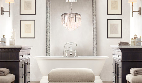
LIGHTING5 Questions to Ask for the Best Room Lighting
Get your overhead, task and accent lighting right for decorative beauty, less eyestrain and a focus exactly where you want
Full Story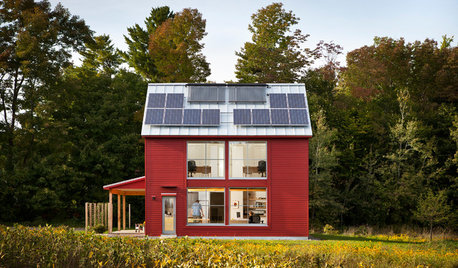
GREEN BUILDINGGoing Solar at Home: Solar Panel Basics
Save money on electricity and reduce your carbon footprint by installing photovoltaic panels. This guide will help you get started
Full Story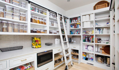
KITCHEN DESIGN9 Questions to Ask When Planning a Kitchen Pantry
Avoid blunders and get the storage space and layout you need by asking these questions before you begin
Full StoryREMODELING GUIDESConsidering a Fixer-Upper? 15 Questions to Ask First
Learn about the hidden costs and treasures of older homes to avoid budget surprises and accidentally tossing valuable features
Full Story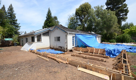
REMODELING GUIDESSurvive Your Home Remodel: 11 Must-Ask Questions
Plan ahead to keep minor hassles from turning into major headaches during an extensive renovation
Full Story
MATERIALSRaw Materials Revealed: Drywall Basics
Learn about the different sizes and types of this construction material for walls, plus which kinds work best for which rooms
Full Story
BATHROOM WORKBOOKStandard Fixture Dimensions and Measurements for a Primary Bath
Create a luxe bathroom that functions well with these key measurements and layout tips
Full Story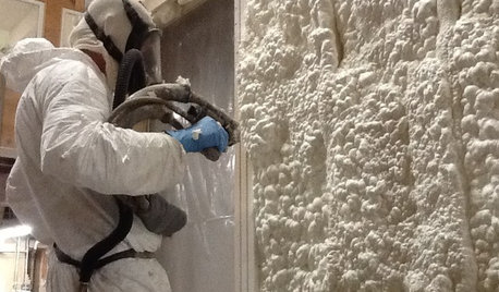
MATERIALSInsulation Basics: What to Know About Spray Foam
Learn what exactly spray foam is, the pros and cons of using it and why you shouldn’t mess around with installation
Full Story
GREEN BUILDINGInsulation Basics: Heat, R-Value and the Building Envelope
Learn how heat moves through a home and the materials that can stop it, to make sure your insulation is as effective as you think
Full Story
RUSTIC STYLE10 Cabin Rental Basics for City Slickers
Stay warm, dry and safe while you’re enjoying winter cabin life with this valuable advice
Full StoryMore Discussions
elalbino63Original Author
kurto
Related Professionals
Ashland Electricians · Aberdeen General Contractors · Deer Park General Contractors · Groton General Contractors · Klamath Falls General Contractors · Mount Prospect General Contractors · Norman General Contractors · Livingston Handyman · Chino Hills Solar Energy Systems · Menifee Solar Energy Systems · Atlanta Home Automation & Home Media · Gladstone Home Automation & Home Media · Ponte Vedra Beach Home Automation & Home Media · St. Johns Home Automation & Home Media · Weston Home Automation & Home Mediaelalbino63Original Author
kurto
brickeyee
elalbino63Original Author
kurto
brickeyee
Billl
elalbino63Original Author
Billl
elalbino63Original Author
brickeyee
kurto
elalbino63Original Author
yosemitebill
elalbino63Original Author
kurto
w0lley32
elalbino63Original Author
hendricus
elalbino63Original Author
brickeyee