


Electric to shed
ohmmm_gw
13 years ago


Related Stories
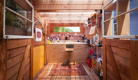
GARDEN SHEDSHouzz Call: Show Us Your Hardworking Garden Shed!
Upload a photo of your backyard shed or greenhouse and tell us how it works for you
Full Story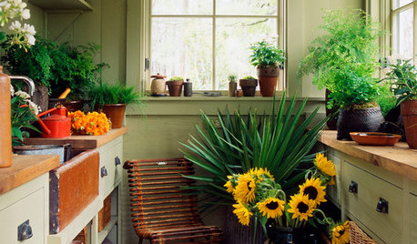
OUTBUILDINGS10 Favorite Shed Features for Comfort and Joy
Make your backyard shed cozier, prettier or more functional with these appealing elements
Full Story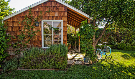
BACKYARD IDEAS7 Backyard Sheds Built With Love
The Hardworking Home: Says one homeowner and shed builder, ‘I am amazed at the peace and joy I feel when working in my garden shed’
Full Story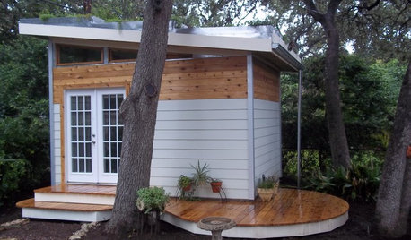
MOST POPULARHow to Add a Backyard Shed for Storage or Living
Need a home office, a playspace or extra room for your stuff? Learn about off-the-shelf, prefab and custom sheds
Full Story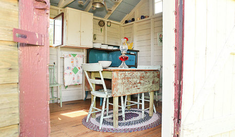
HOUZZ TOURSMy Houzz: A Backyard Getaway Emerges From a Grain Shed
Cozy and brimming with country charm, this snug antiques-filled hideout encourages quiet pastimes
Full Story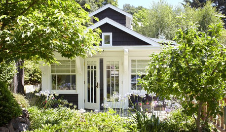
BACKYARD STUDIOS12 Garden Sheds and Cottages We Love Now
Get inspiration from these inviting backyard spaces that house offices, guest quarters, garden storage and more
Full Story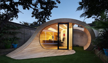
OUTBUILDINGSWorld of Design: 11 Inspiring Sheds From Santa Barbara to Stockholm
Outbuildings from around the world show how sheds and cottages set the scene for everything from baking in a sauna to beekeeping
Full Story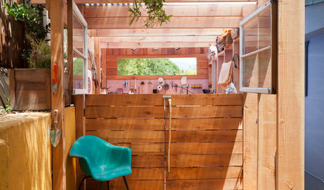
STUDIOS AND WORKSHOPSA Compact Shed Makes Room for Storage, Creativity and Style
With a tidy workspace, neatly hidden trash cans and even a mini patio, this inspired shed meets everything on a creative couple's wish list
Full Story
ECLECTIC HOMESHouzz Tour: Backyard Shed Transformed Into a ‘Shedeau’
A once-crumbling outbuilding is now a personality-rich guesthouse for visiting family members
Full Story
STUDIOS AND WORKSHOPSCreative Houzz Users Share Their ‘She Sheds’
Much thought, creativity and love goes into creating small places of your own
Full Story
spencer_electrician
terribletom
Related Professionals
Bloomington General Contractors · Flint General Contractors · New Milford General Contractors · Pepper Pike General Contractors · Tuckahoe General Contractors · University Park General Contractors · Wright General Contractors · El Monte Home Automation & Home Media · Jollyville Home Automation & Home Media · Los Angeles Home Automation & Home Media · Margate Home Automation & Home Media · Norwalk Home Automation & Home Media · Pittsburgh Home Automation & Home Media · Reston Home Automation & Home Media · East Setauket Home Automation & Home Mediasmithy123
ohmmm_gwOriginal Author
brickeyee
weedmeister
lbpod
ohmmm_gwOriginal Author
terribletom
pharkus
ohmmm_gwOriginal Author
DavidR
pharkus
ohmmm_gwOriginal Author
ohmmm_gwOriginal Author
spencer_electrician
ohmmm_gwOriginal Author
pharkus
ohmmm_gwOriginal Author
ohmmm_gwOriginal Author
ohmmm_gwOriginal Author
ohmmm_gwOriginal Author
spencer_electrician
terribletom
ohmmm_gwOriginal Author
ohmmm_gwOriginal Author
ohmmm_gwOriginal Author
saltcedar
DavidR
ohmmm_gwOriginal Author
ohmmm_gwOriginal Author
ohmmm_gwOriginal Author
DavidR
ohmmm_gwOriginal Author
ohmmm_gwOriginal Author
DavidR
ohmmm_gwOriginal Author
terribletom
brickeyee
terribletom
terribletom
ohmmm_gwOriginal Author
ohmmm_gwOriginal Author
petey_racer
ohmmm_gwOriginal Author
DavidR
jaysgarden
pharkus
ohmmm_gwOriginal Author
zimzimma_optonline_net