


Wiring a rocker switch
dhar2112
11 years ago
Sort by:Oldest
Comments (7)
Related Stories
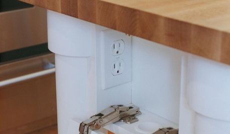
KITCHEN DESIGNHow to Hide Those Plugs and Switches
5 ways to camouflage your outlets — or just make them disappear
Full Story
DECORATING GUIDESHomeowners Are Flipping for Push-Button Light Switches
Button-style switches are hot off the presses again, making news in new homes and antique remodels
Full Story
LIGHTINGWhat to Know About Switching to LED Lightbulbs
If you’ve been thinking about changing over to LEDs but aren't sure how to do it and which to buy, this story is for you
Full Story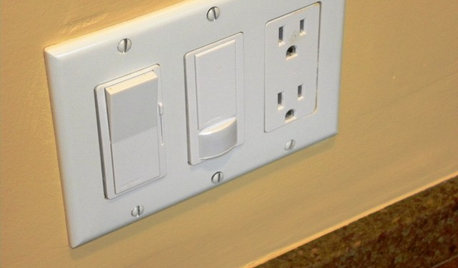
GREAT HOME PROJECTSHow to Install a Dimmer Switch
New project for a new year: Take control of your lighting to set the right mood for entertaining, dining and work
Full Story
GREAT HOME PROJECTSHow to Switch to a Tankless Water Heater
New project for a new year: Swap your conventional heater for an energy-saving model — and don’t be fooled by misinformation
Full Story
HOME TECHSwitch On the Phone-Controlled Home
Lock your front door from afar, let your thermostat set itself and more when you use your phone as a control device
Full Story
ACCESSORIESHow to Hide Those Messy Wires
Untangle Yourself From Ugly Electrical Cords With a Few Tricks and Accessories
Full Story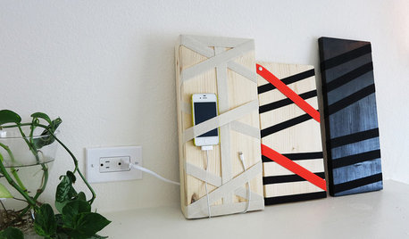
DIY PROJECTSHide All Those Wires in a DIY Charging Station
Keep your gadgets handy and charged with a flexible storage board you can design yourself
Full Story
LIGHTING10 Ways With Wall Lights That Don’t Need to Be Wired In
Learn how to add illumination to your home without carving into the walls
Full Story
ACCESSORIES8 Low-Cost Luxuries With a Big Payoff
Consider the small stuff — like switch plates and throw pillows — to give your home a touch of class
Full StoryMore Discussions
petey_racer
bus_driver
Related Professionals
Alhambra General Contractors · Channelview General Contractors · Dallas General Contractors · Franklin General Contractors · Hermitage General Contractors · Medford General Contractors · Northfield General Contractors · Phenix City General Contractors · Rohnert Park General Contractors · North New Hyde Park Handyman · Fort Lee Solar Energy Systems · Madison Solar Energy Systems · Reedley Solar Energy Systems · Algonquin Home Automation & Home Media · West Chester Home Automation & Home Mediadhar2112Original Author
bus_driver
yosemitebill
dhar2112Original Author
yosemitebill