


False ground on plug-in GFCI device?
catfishsew
13 years ago
Sort by:Oldest
Comments (10)
Related Stories
GREAT HOME PROJECTSPower to the People: Outlets Right Where You Want Them
No more crawling and craning. With outlets in furniture, drawers and cabinets, access to power has never been easier
Full Story
REMODELING GUIDESBanish Gizmo Blemishes on Your Walls
Unsightly switches, vents and outlets can ruin your interior design's clear complexion. Keep the look pure with an architect's tips
Full Story
BATHROOM DESIGN10 Living Room Touches to Bring to the Bath
Go ahead, borrow those bookshelves. Unexpected elements can boost interest and comfort in your bathroom
Full Story
GREAT HOME PROJECTSHow to Create a Secret Doorway Behind a Bookcase
Hide your valuables (or unsightly necessities) in a room or nook that no one will guess is there
Full Story
KITCHEN DESIGNHouzzers Say: Top Dream Kitchen Must-Haves
Tricked-out cabinets, clean countertops and convenience top the list
Full Story
BATHROOM DESIGN10 Amenities to Make Your Bathroom Extraordinary
Go beyond the basics for a luxury bathroom experience, with extra-special options starting at only $25
Full Story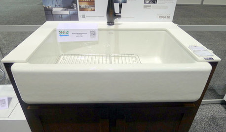
Highlights From the 2012 Kitchen and Bath Industry Show
Innovations in sinks, outlets and surface materials for kitchens and baths shone at this year's show
Full Story
BATHROOM DESIGNShould You Get a Recessed or Wall-Mounted Medicine Cabinet?
Here’s what you need to know to pick the right bathroom medicine cabinet and get it installed
Full Story
OUTDOOR PROJECTSBring In the Birds With a Homemade Bubble Rock
An avian expert from Southern Indiana shows how to make a burbling fountain that migrating birds will love
Full Story
DOORSDiscover the Ins and Outs of Pocket Doors
Get both sides of the pocket door story to figure out if it's the right space separator for your house
Full Story

Ron Natalie
DavidR
Related Professionals
Orlando Electricians · Fort Salonga General Contractors · Irving General Contractors · Merrimack General Contractors · Merritt Island General Contractors · Mishawaka General Contractors · Orangevale General Contractors · Roselle General Contractors · Wolf Trap General Contractors · Glen Avon Solar Energy Systems · Brushy Creek Home Automation & Home Media · Campbell Home Automation & Home Media · Castle Rock Home Automation & Home Media · Margate Home Automation & Home Media · Tampa Home Automation & Home MediacatfishsewOriginal Author
brickeyee
smithy123
pharkus
steveomc
smithy123
pharkus
Ron Natalie