


hot ground?
mom_in_wv
14 years ago
Related Stories
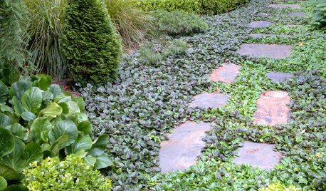
GROUND COVERSGround Force: 10 Top Ground Covers for Your Garden
Protect your soil from weeds and drought this summer with a living mulch of ground covers
Full Story
ORANGEOrange: Still Hot, Hot, Hot
Get fired up to bring in more orange with energizing paint, furnishings, rugs and accessories
Full Story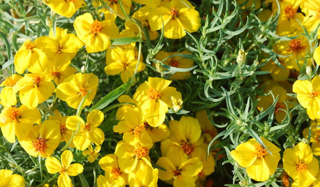
GARDENING GUIDESGreat Design Plant: Rocky Mountain Zinnia Brightens Hot, Dry Spots
Sunshiny flowers provide a showy drift of color in desert and prairie gardens — this native perennial is hardier than it looks
Full Story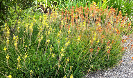
GARDENING GUIDES6 Dependable Ground Covers for Warm Climates
Swap some lawn for these drought-tolerant clumping plants — and watch your maintenance efforts diminish while they easily grow
Full Story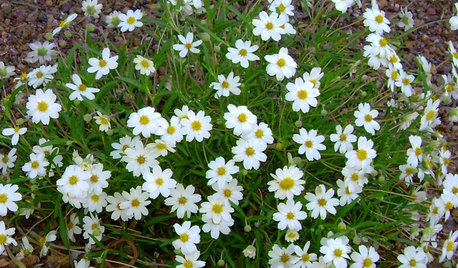
GROUND COVERSGreat Design Plant: Blackfoot Daisy for Prettier Dry Ground
Don’t let its delicate looks fool you. This ground cover can survive extreme cold and heat, and with little water to boot
Full Story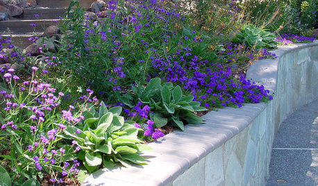
GARDENING GUIDESGreat Design Plant: Glandularia Rigida Paints the Ground Purple
Sandpaper verbena's deep purple flowers create a colorful carpet in drought-tolerant gardens
Full Story
DECORATING GUIDESNo Neutral Ground? Why the Color Camps Are So Opinionated
Can't we all just get along when it comes to color versus neutrals?
Full Story
GREEN BUILDINGThe Big Freeze: Inventors Break New Ground to Keep Things Cool
Old-fashioned fridges can be energy guzzlers, but there are more eco-friendly ways of keeping food fresh, as these global innovations show
Full Story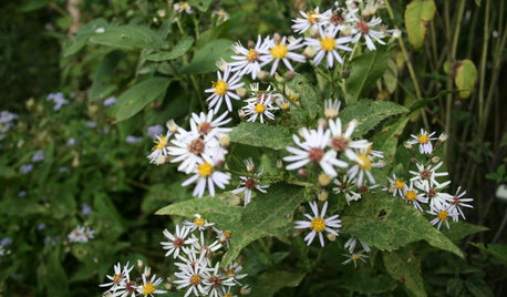
GARDENING GUIDES6 Native Ground Covers for Tough, Dry Spots
Sun beating down on your sandy gravel? Thick shade darkening your clay soil? There’s a ground cover here for you
Full Story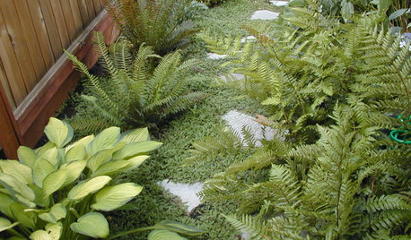
LANDSCAPE DESIGN6 Great Ways With Garden Ground Covers
Use them as problem solvers, weed killers, color and texture providers ... ground cover plants have both practical and visual appeal
Full StoryMore Discussions


bettyg
mom_in_wvOriginal Author
Related Professionals
Murraysville General Contractors · Clive General Contractors · Coos Bay General Contractors · Glenn Dale General Contractors · Monroe General Contractors · Montclair General Contractors · Nashua General Contractors · New Bern General Contractors · Newington General Contractors · Wolf Trap Handyman · Coachella Solar Energy Systems · Sanger Solar Energy Systems · Saratoga Springs Solar Energy Systems · Mount Lebanon Home Automation & Home Media · San Diego Home Automation & Home Mediamom_in_wvOriginal Author
brickeyee
normel
mom_in_wvOriginal Author
normel
joed
mom_in_wvOriginal Author
Ron Natalie
mom_in_wvOriginal Author
samneric
joed
brickeyee
mom_in_wvOriginal Author
brickeyee
mom_in_wvOriginal Author
brickeyee
mom_in_wvOriginal Author