


tracing out membrane buttons
woodturner79
12 years ago
Featured Answer
Sort by:Oldest
Comments (19)

kurto
12 years agoRon Natalie
12 years agoRelated Professionals
Albany General Contractors · Alhambra General Contractors · Bound Brook General Contractors · Conneaut General Contractors · Deer Park General Contractors · Enfield General Contractors · Hamilton Square General Contractors · Jeffersonville General Contractors · Lakeside General Contractors · Lighthouse Point General Contractors · North Tustin General Contractors · Waipahu General Contractors · Brockton Solar Energy Systems · Algonquin Home Automation & Home Media · Los Angeles Home Automation & Home Mediabrickeyee
12 years agowoodturner79
12 years agoyosemitebill
12 years agowoodturner79
12 years agoRon Natalie
12 years agowoodturner79
12 years agobrickeyee
12 years agowoodturner79
12 years agobrickeyee
12 years agoRon Natalie
12 years agowoodturner79
12 years agoyosemitebill
12 years agobrickeyee
12 years agobrickeyee
12 years agowoodturner79
12 years ago
Ross W
3 years ago
Related Stories

ARCHITECTUREHave Your Flat Roof and Your Snow Too
Laboring under the delusion that flat roofs are leaky, expensive and a pain to maintain? Find out the truth here
Full Story
GARDENING GUIDESSouthern California Gardener's September Checklist
Before prime planting time, clean out the old garden, prepare for the new, and dream up ideas for fall flowers and veggies
Full Story0

EVENTS12 Must-See Art and Design Events This January
Get out and get inspired! See what’s on the Houzz creative calendar in the new year
Full Story
DIY PROJECTSMake a Gorgeous (Cheap!) Pillow Using Vintage Clothes
With secondhand fabric and a steady hand on the sewing machine, your pillow choices are endless
Full Story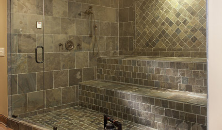
SHOWERSSteam Showers Bring a Beloved Spa Feature Home
Get the benefits of a time-honored ritual without firing up the coals, thanks to easier-than-ever home steam systems
Full Story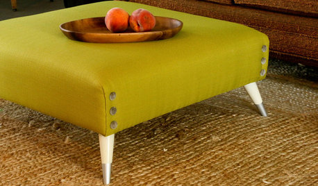
DIY PROJECTSTurn a Shipping Pallet Into a Stylish Ottoman
Get the step-by-step instructions for upholstering your own mod living room centerpiece
Full Story
FLOORSHow to Get a Tile Floor Installed
Inventive options and durability make tile a good choice for floors. Here’s what to expect
Full Story
HEALTHY HOMEWhat You Need to Know About Dust and How to Fight It
Breathe easier with these 10 tips for busting mites, dander and other microscopic undesirables
Full Story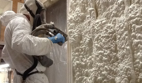
MATERIALSInsulation Basics: What to Know About Spray Foam
Learn what exactly spray foam is, the pros and cons of using it and why you shouldn’t mess around with installation
Full Story
BATHROOM DESIGNConvert Your Tub Space to a Shower — the Fixtures-Shopping Phase
Step 2 in swapping your tub for a sleek new shower: Determine your mechanical needs and buy quality fixtures
Full Story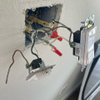


woodturner79Original Author