


240V circuit breaker amperage question
Vrtigo1
12 years ago
Related Stories
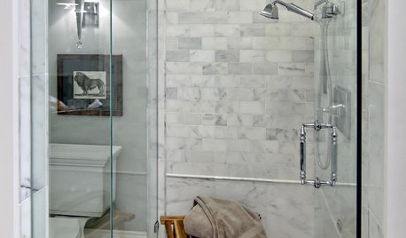
BATHROOM DESIGNHow to Settle on a Shower Bench
We help a Houzz user ask all the right questions for designing a stylish, practical and safe shower bench
Full Story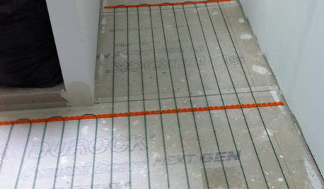
BATHROOM DESIGNWarm Up Your Bathroom With Heated Floors
If your bathroom floor is leaving you cold, try warming up to an electric heating system
Full Story
FUN HOUZZ31 True Tales of Remodeling Gone Wild
Drugs, sex, excess — the home design industry is rife with stories that will blow your mind, or at least leave you scratching your head
Full Story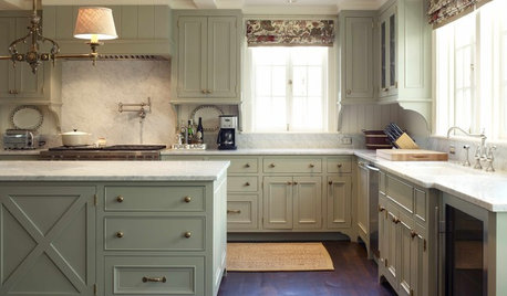
KITCHEN DESIGN9 Ways to Save on Your Kitchen Remodel
A designer shares key areas where you can economize — and still get the kitchen of your dreams
Full Story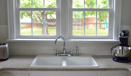
KITCHEN BACKSPLASHESHow to Install a Tile Backsplash
If you've got a steady hand, a few easy-to-find supplies and patience, you can install a tile backsplash in a kitchen or bathroom
Full Story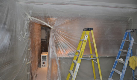
MOST POPULAR11 Things to Expect With Your Remodel
Prepare yourself. Knowing what lies ahead during renovations can save your nerves and smooth the process
Full Story
kurto
Vrtigo1Original Author
Related Professionals
Berkeley General Contractors · Broadview Heights General Contractors · De Luz General Contractors · Great Falls General Contractors · Kilgore General Contractors · Selma General Contractors · Shaker Heights General Contractors · South Windsor General Contractors · Shelton Solar Energy Systems · Asheville Home Automation & Home Media · Chattanooga Home Automation & Home Media · El Monte Home Automation & Home Media · Philadelphia Home Automation & Home Media · Scottsdale Home Automation & Home Media · Walnut Creek Home Automation & Home Mediabrickeyee
Billl
kurto
Vrtigo1Original Author
brickeyee
mike_kaiser_gw
brickeyee
Jcris3973
bus_driver
Stevie51
Stevie51
Stevie51