Shop Products
Houzz Logo Print
davmp

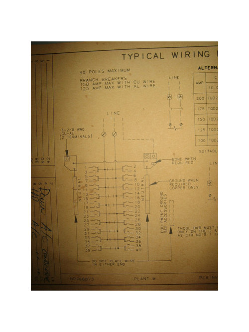
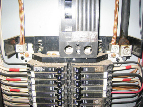
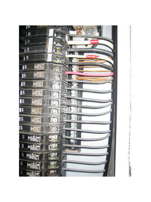
Can I add more breakers to my main panel? (images)

davmp
14 years ago

I was hoping to add two more 15A breakers to my home's main electrical panel, but after taking off the cover I realized I've got a few questions and was hoping someone could help out with some answers.

My panel is a GE 120/240VAC 3 wire 1 phase, 200A max.

It say cat. no. TLM2020C MOD. 1 (Type 1 indoor enclosure)

It has a UL Listed No. of EE-851267

Unfortunately, I can't find a "model number" designation anywhere.

  1. The first question is: How do I figure out if there's a limit or rating of any kind that would prevent me from adding new breakers? That is, I see there are spaces available on the left line of breakers, but does that mean I can simply add new breakers? To my understanding, as long as adding the new circuits doesn't increase the total demand over 200A, I should be okay, right? Here's an overview of the box and it's wiring diagram:


Second question: I see that whomever wired the box originally took great pains to keep all the "neutral" white wires on the left side bus whereas the only things connected to the right side bus are naked copper (which I'm assuming is ground wires that just couldn't fit in the two larger clamps at the top?) Anyway, since the buses are bridged together (including all grounds too!) and the terminals on the left bus are all fully used but those on the right are not, can I simply connect the whites from the new circuits to the right bus? Is there any reason not to do so? Would it be better to double up connections in a single terminal on the left bus (like someone did for two bare copper wires on the right bus)?


Comments (28)

  • pharkus
    14 years ago

    Well, you conveniently didn't get the bottom half of the panel, so I can't count how many breakers are there.

    Don't exceed 42, that's the legal requirement. That said, it does appear that there are open spaces into which you can add more breakers.

    Regarding neutral/ground being seperated... In some cases they HAVE to be. Yours does NOT look like one of those cases, but it's neat to do so anyway.

    You are not supposed to put two wires in one hole unless some labeling or another on the panel itself indicates that doing so is permissible. It's usually not.

  • davmp
    Original Author
    14 years ago

    Sorry, didn't notice that my overview photo was cut-off like that. Here's one that just shows all 32 current breakers. It looks like only 4 open spots on the left.


  • pharkus
    14 years ago

    Yes, you can add more breakers.

  • davmp
    Original Author
    14 years ago

    Great! And so there are no issues connecting the white and ground wires of the new circuits to the same bus bar (the one on the right with empty terminals)? Or should I just connect the whites there and interweave the grounds in with the other thick bundles that are in the clamps at the top of the breakers?

  • pharkus
    14 years ago

    Slow down! I actually already addressed that. In some cases (mainly subpanels, but also a few others), the neutrals and the grounds need to be seperate! I already said that! If the last guy did it that way, he may very well have done it for a reason, so continue his trend!

    Now, I think I see a major problem here... I was wondering earlier, but didn't mention it, why there were two bare ground wires attached at the top... and the way you just re-worded your question makes me wonder... Did someone seriously take all of the branch circuit ground wires, twist them all together, and shove them into the two largish lugs at the top of the bar? If so, that is a BIG NO-NO. Truth be told, one would be hard-pressed to convince me there's any major safety issue there, but it's definitely not legal, and you shouldn't do any more of it.


    If you would have a closer look, find out if the bar with grounds on it (on the right, behind the hot wires) is connected directly to the bar with neutrals on it (on the left, behind the hot wires). If they are conected, then you can attach your new grounds and neutrals all to whichever of the two is most convenient. If they are not connected together, then you need to route your neutrals to the left bar and grounds to the right one, continuing the existing trend.

    I, personally, would continue it regardless - it looks neat that way.


    Again, if I'm seeing that correctly (branch grounds twisted together and shoved in big lugs), DON'T DO THAT ANYMORE, and you might give some consideration to UNdoing it and connecting them all where they go.

  • christophersprks
    14 years ago

    The grounds are allowed to be bunched in like that.... the Neutrals on the other hand, you are correct, one hole -one conductor.

  • bigbird_1
    14 years ago

    That's one of the cleanest and well wired panels that I've seen. The DP breakers are all together and not randomly spread through the panel. All hot white wires are relabeled with red tape. You are lucky.

  • pharkus
    14 years ago

    The grounds are allowed to be bunched in like that....

    Really?! Wow, for once, something that makes perfect sense is actually legal! I'm impressed!

  • brickeyee
    14 years ago

    Looks like some 240 V loads (the red marked white wires) without handle ties.

  • davmp
    Original Author
    14 years ago

    Hi All, thanks for the responses!

    @pharkus: I thought I was already clear that the two bus bars (the one on the left with all the whites, and the one on the right with about 5 grounds) are electronically connected? I already tested this with a continuity test. So my question was could there be some other reason besides neatness for having split the whites and grounds this way? I don't think so, but it never hurts to ask. I want to make sure before I put whites on the right bus bar, which I have to do because there's no more empty terminals on the left one. Or should I be trying to mount an add-on bus bar on the leftside under the current one? Or perhaps replace the existing one with something with more terminals?

    And yes, almost all the ground wires for all circuits are those bare copper twists coming down from the top of the box and going into only two clamps -- except for about 5 going into the right bus bar. I notice there's one empty lug spot (on the left side) where I could attach a new clamp if I wanted to keep that "style" up.

    @brickeye: If you look closely, you can barely see the glint of the bars connecting the handles on the DPs. Just keep in mind that the very top left and right ones are SPs.

  • bigbird_1
    14 years ago

    "Looks like some 240 V loads (the red marked white wires) without handle ties."

    Look closer and you'll see the white reflection between the handles.

  • samneric
    14 years ago

    The grounds are allowed to be bunched in like that....

    Not by the NEC. Those 2 terminals are labeled "6-2/0 AWG Cu-Al", and there is nothing to allow multiple wires in that labeling. Looks pretty, but it's not legal.

    Pharkus was correct... at least until he wavered :)

  • brickeyee
    14 years ago

    "I thought I was already clear that the two bus bars (the one on the left with all the whites, and the one on the right with about 5 grounds) are electronically connected?"

    What does electronics have to do with a bus bar connection?

    You mean 'electrically connected.'

    The ties do not show on my monitor, but as long as they are there.

  • davmp
    Original Author
    14 years ago

    You mean 'electrically connected.'
    Yes, indeed I did. Thanks for catching that.

    The ties do not show on my monitor
    How about on the wiring diagram photo? Which comes from the inside cover of the panel btw. It is not something I drew up. :-)

    So any advice on what should I be doing here? There clearly aren't enough terminals to individually connect all those twisted together grounds to, even if I wanted to do so. Plus, they've all been cut too short to reach the existing terminals. Should I just leave it alone and hope the AHJ doesn't notice?

  • brickeyee
    14 years ago

    "How about on the wiring diagram photo? Which comes from the inside cover of the panel btw. It is not something I drew up."

    The diagram does not indicate that correctly tied breakers have been installed, just that they should be installed.

  • bigbird_1
    14 years ago

    "Not by the NEC. Those 2 terminals are labeled "6-2/0 AWG Cu-Al", and there is nothing to allow multiple wires in that labeling."

    The terminals are labeled #6-2/0. Since those sizes represent stranded wires, not solid conductors, what difference does it make whether there is one 2/0 stranded or eight #14 grounds under that lug? What does the NEC say specifically? I would think that whoever did that panel also had it inspected. Any comments on inspection from the OP?

  • pharkus
    14 years ago

    There's a difference between what seems obvious and what is written.

    I believe, if it says "2/0" it means 2/0, not "something the installer made up that happens to be the same size as 2/0".

    I agree (and indicated this) that there probably ISN'T a function difference. That method of terminating ground wires seems, to me, to make sense, and I can see no reason based in electrical theory why it would ever be a problem - but code is code, unfortunately, and it's supposed to mean what it says.


    davmp, you are correct, in that the bars on each side are, in fact, connected. Shows it right in the diagram. I neglected to look at the diagrams - I never do - I only looked at the panel guts themselves, and the photos didn't make it clear since there were other objects in front of the bar.


    You're fine on adding more breakers, and neutrals/grounds can go on either side. As far as whether or not you can shove more into big lugs at the top, well, I'll leave that to the others to hash out.

  • christophersprks
    14 years ago

    * Posted by samneric (My Page) on Mon, Jul 13, 09 at 19:08
    "The grounds are allowed to be bunched in like that...."

    Not by the NEC. Those 2 terminals are labeled "6-2/0 AWG Cu-Al", and there is nothing to allow multiple wires in that labeling. Looks pretty, but it's not legal.

    Pharkus was correct... at least until he wavered :)

    Sam, show me in the NEC where it says you can't.
    I think you should contact your AHJ in your area and ask him/her. Mine says YOU CAN :P

  • christophersprks
    14 years ago

    and for Those 2 terminals are labeled "6-2/0 AWG Cu-Al".

    I'm sure you know that means the lug is capable of handle a 6 AWG all the way up 2/ought.
    Get enough strands together to equal a #6 stranded cable and you're good to go.

  • bigbird_1
    14 years ago

    "I'm sure you know that means the lug is capable of handle a 6 AWG all the way up 2/ought. Get enough strands together to equal a #6 stranded cable and you're good to go."

    That was my thinking as well.

  • samneric
    14 years ago

    I'm sure you know that means the lug is capable of handle a 6 AWG all the way up 2/ought.
    Get enough strands together to equal a #6 stranded cable and you're good to go.

    That's funny. How many #14's or #12's would that be? Does the "good to go" rule apply to the lugs on breakers too?

    Sam, show me in the NEC where it says you can't.

    NEC 110.14(A)
    Terminals for more than one conductor or terminals used to connect aluminum shall be so identified.

    I don't have a problem with the OP's panel either way. But I thought you meant it was allowed by the NEC, not just by your particular AHJ or personal rules.

  • davmp
    Original Author
    14 years ago

    Any comments on inspection from the OP?
    Not anything I can say from personal experience... yet. This project is the first change to the electrical since we moved into the house, so no one but the purchase home inspector has looked at it and told me anything. While he was not an AHJ, he didn't say anything about it. But I'm not sure that's worth much.

    I'm assuming it did pass an AHJ inspection when the house was built, or if the previous owner(s) had any work done. (The house was built in the mid-80's and we moved in about 8 years ago.) We all know what assumptions are worth.

    Will update when we do get an AHJ inspection.

  • redstar1970_att_net
    12 years ago

    Under question 2 above, image three shows the grounding bar and at the lowest used port there are two grounding wires inserted. Is this permissible. I have a situation where I have run out of empty grounding bar ports but have plenty of space on the bus bar for added breakers and would like to add one grounding wire to a convenient already used port. I suspect that the answer is that it is permissible but I am no electrician.

  • terribletom
    12 years ago

    "Under question 2 above, image three shows the grounding bar and at the lowest used port there are two grounding wires inserted. Is this permissible."

    Generally yes, as long as the number of equipment grounding wires in any one hole doesn't exceed the manufacturer's instructions. Most ground bar specs allow two wires under a single screw so long as the wires are the same size and type (e.g., don't mix CU/AL or solid/stranded).

    The same is NOT true of neutrals, which should not share holes with each other or with grounds.

  • Ron Natalie
    12 years ago

    Huh? Samneric has it right. A terminal is listed for more than one conductor or not. It matters NOT whether it's a ground, hot, or neutral. And, no two #12's twisted together do not equal a 2/0.

  • brickeyee
    12 years ago

    "A terminal is listed for more than one conductor or not."

    This.

    And all equipment ust be used within the terms of the manufaturers instructions and the listing of the equipment.

    The 43 breaker limit was removed in a recent code rev, but that panel appears to be using all 'half size' breakers and may not be listed for use that way.

  • brickeyee
    12 years ago

    42 breaker limit.

    Typo.