


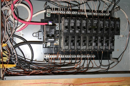
Subpanel wiring question
hoosierdoc
12 years ago
Sort by:Oldest
Comments (10)
Related Stories

TASTEMAKERS5 Questions From ICFF: Lindsey Adelman
The inventive designer takes a break from New York's International Contemporary Furniture Fair to talk about her artistic lighting fixtures
Full Story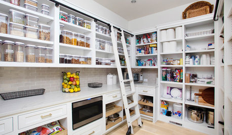
KITCHEN DESIGN9 Questions to Ask When Planning a Kitchen Pantry
Avoid blunders and get the storage space and layout you need by asking these questions before you begin
Full StoryREMODELING GUIDESConsidering a Fixer-Upper? 15 Questions to Ask First
Learn about the hidden costs and treasures of older homes to avoid budget surprises and accidentally tossing valuable features
Full Story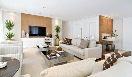
Today's Question: TV Fireplace Dilemma
Should the TV Go Above the Fireplace — or Not? Have Your Say!
Full Story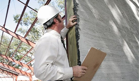
MOVINGHiring a Home Inspector? Ask These 10 Questions
How to make sure the pro who performs your home inspection is properly qualified and insured, so you can protect your big investment
Full Story
LIGHTING5 Questions to Ask for the Best Room Lighting
Get your overhead, task and accent lighting right for decorative beauty, less eyestrain and a focus exactly where you want
Full Story
ORGANIZINGPre-Storage Checklist: 10 Questions to Ask Yourself Before You Store
Wait, stop. Do you really need to keep that item you’re about to put into storage?
Full Story
CURB APPEAL7 Questions to Help You Pick the Right Front-Yard Fence
Get over the hurdle of choosing a fence design by considering your needs, your home’s architecture and more
Full Story
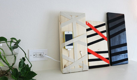
DIY PROJECTSHide All Those Wires in a DIY Charging Station
Keep your gadgets handy and charged with a flexible storage board you can design yourself
Full StorySponsored
Custom Craftsmanship & Construction Solutions in Franklin County
More Discussions
weedmeister
Ron Natalie
Related Professionals
Claremont General Contractors · Converse General Contractors · Coshocton General Contractors · Decatur General Contractors · Havre de Grace General Contractors · Las Cruces General Contractors · Midlothian General Contractors · Renton General Contractors · River Forest General Contractors · Uniondale General Contractors · Lomita Solar Energy Systems · Voorhees Solar Energy Systems · Boston Home Automation & Home Media · Libertyville Home Automation & Home Media · South Lake Tahoe Home Automation & Home Mediabus_driver
Ron Natalie
bus_driver
John Liu
John Liu
normel
brickeyee
fa_f3_20