


Junction Box Grounding with 6AWG Splice
kevin1900
10 years ago
Related Stories

GARDENING AND LANDSCAPINGSpring Patio Fix-Ups: 6 Ways to Light Your Outdoor Room
Let the good times roll well into the evening with string lights, sconces, pendants and more to illuminate your patio or deck
Full Story
GREEN BUILDINGWorld of Design: The Joy of Moss and Its Modern Uses
This great design plant is 400 million years in the making. See how it’s inspiring art, soothing spaces and building design
Full Story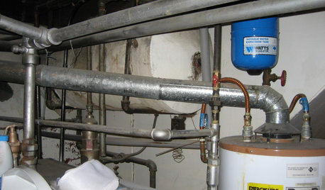
REMODELING GUIDES7 Bad Things Your Home May Be Hiding
What you don't know about your home could cost you during a remodel. Here's what to plan for
Full Story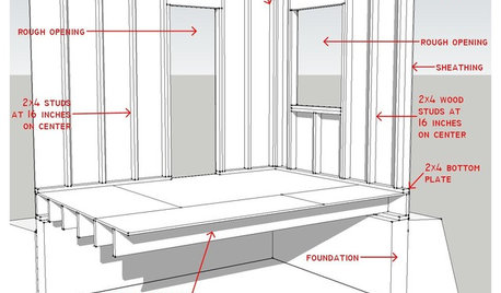
REMODELING GUIDESKnow Your House: Components of Efficient Walls
Learn about studs, rough openings and more in traditional platform-frame exterior walls
Full Story
CONTRACTOR TIPSYour Complete Guide to Building Permits
Learn about permit requirements, the submittal process, final inspection and more
Full Story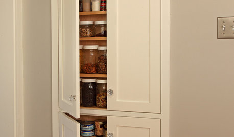
STORAGETap Into Stud Space for More Wall Storage
It’s recess time. Look to hidden wall space to build a nook that’s both practical and appealing to the eye
Full Story
GREAT HOME PROJECTSPower to the People: Outlets Right Where You Want Them
No more crawling and craning. With outlets in furniture, drawers and cabinets, access to power has never been easier
Full Story
CEILINGSAdd a Touch of Elegance With a Ceiling Medallion
Installed with adhesive and often less than $100, this decorative detail makes an impact
Full Story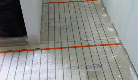
BATHROOM DESIGNWarm Up Your Bathroom With Heated Floors
If your bathroom floor is leaving you cold, try warming up to an electric heating system
Full Story
MOST POPULAR9 Real Ways You Can Help After a House Fire
Suggestions from someone who lost her home to fire — and experienced the staggering generosity of community
Full Story
Ron Natalie
kevin1900Original Author
Related Professionals
Murraysville General Contractors · Clinton General Contractors · Medway General Contractors · Rohnert Park General Contractors · Rosemead General Contractors · Wheaton General Contractors · Winfield General Contractors · Vienna Handyman · North New Hyde Park Handyman · Brookline Home Automation & Home Media · Chicago Home Automation & Home Media · Rowland Heights Home Automation & Home Media · Tamiami Home Automation & Home Media · Weatherford Home Automation & Home Media · Walnut Creek Home Automation & Home MediaRon Natalie
weedmeister
weedmeister
Ron Natalie
kevin1900Original Author
Ron Natalie
kevin1900Original Author