


blown double pole switch for electric motor
kappstan
13 years ago
Sort by:Oldest
Comments (6)
Related Stories
LIGHTINGWhat to Know About Switching to LED Lightbulbs
If you’ve been thinking about changing over to LEDs but aren't sure how to do it and which to buy, this story is for you
Full Story
LIVING ROOMSHow to Convert Your Wood-Burning Fireplace
Learn about inserts and other options for switching your fireplace from wood to gas or electric
Full Story
GARAGESHouzz Call: Show Us Your Garage Conversion
Have you switched from auto mode into workshop, office, gym or studio mode? We'd love to see the result
Full Story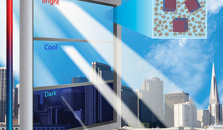
HOME TECHIs It Curtains for Curtains? Smart Glass Eliminates Window Coverings
Windows can now control light and heat through electricity and high-tech formulations, making blinds and shades optional
Full Story
BATHROOM DESIGNLight-Up Mirrors Offer Bright Design Solutions
If you're taking a dim view of a problem bathroom area, try the flash of design brilliance that is the electric mirror
Full Story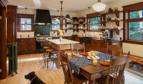
KITCHEN DESIGNKitchen of the Week: Period Details Keep History Alive in Portland
Modern functionality and doubled square footage bring a 1910 kitchen into the present while respecting its past
Full Story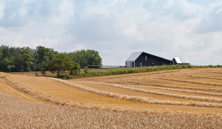
GREEN BUILDINGOff the Grid: Ready to Pull the Plug on City Power?
What to consider if you want to stop relying on public utilities — or just have a more energy-efficient home
Full Story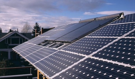
GREEN BUILDINGLet’s Clear Up Some Confusion About Solar Panels
Different panel types do different things. If you want solar energy for your home, get the basics here first
Full Story
WINDOW TREATMENTS6 Ways to Deal With a Bad View Out the Window
You can come out from behind the closed curtains now. These strategies let in the light while blocking the ugly
Full Story
LIGHTINGHow to Choose the Right Solar Lights
Learn about different types of outdoor solar lights, where to use them and why you might want to avoid the bargain bin
Full Story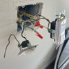
DavidR
Ron Natalie
Related Professionals
Markham Electricians · Abington General Contractors · Arlington General Contractors · Coos Bay General Contractors · Fremont General Contractors · Gloucester City General Contractors · Kailua Kona General Contractors · Kilgore General Contractors · Los Alamitos General Contractors · Alafaya Solar Energy Systems · Carson Solar Energy Systems · Hemet Solar Energy Systems · Lomita Solar Energy Systems · Palo Alto Solar Energy Systems · Leander Home Automation & Home Mediabus_driver
kappstanOriginal Author
kappstanOriginal Author
kappstanOriginal Author