


Breaker tripping in circuit with a contact
richard904
12 years ago
Sort by:Oldest
Comments (10)
Related Stories
LIFE10 Ways to Keep Your Home Safe While You're Traveling
Set off on your trip with peace of mind, knowing you've taken the right steps toward keeping your home secure
Full StoryHOUSEKEEPINGAll Together Now: Tackle Home Projects With a DIY Co-op
You're in good company when you pair up with a pal to clean, organize, repair and replace
Full Story
BATHROOM DESIGNDoorless Showers Open a World of Possibilities
Universal design and an open bathroom feel are just two benefits. Here’s how to make the most of these design darlings
Full Story
LIFEHow to Prepare for and Live With a Power Outage
When electricity loss puts food, water and heat in jeopardy, don't be in the dark about how to stay as safe and comfortable as possible
Full Story
GREAT HOME PROJECTSPower to the People: Outlets Right Where You Want Them
No more crawling and craning. With outlets in furniture, drawers and cabinets, access to power has never been easier
Full Story
MOST POPULAR10 Things to Ask Your Contractor Before You Start Your Project
Ask these questions before signing with a contractor for better communication and fewer surprises along the way
Full Story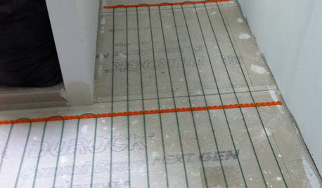
BATHROOM DESIGNWarm Up Your Bathroom With Heated Floors
If your bathroom floor is leaving you cold, try warming up to an electric heating system
Full Story
CONTRACTOR TIPSBuilding Permits: 10 Critical Code Requirements for Every Project
In Part 3 of our series examining the building permit process, we highlight 10 code requirements you should never ignore
Full Story
GREAT HOME PROJECTSMake a Push for a New Doorbell
Is it time to replace a doorbell or even add a door intercom or video system? Installation may be easier than you think
Full Story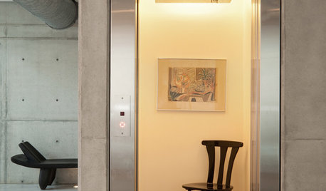
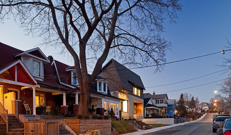
REMODELING GUIDESHome Elevators: A Rising Trend
The increasing popularity of aging in place and universal design are giving home elevators a boost, spurring innovation and lower cost
Full Story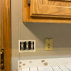

bus_driver
brickeyee
Related Professionals
Framingham Center Electricians · Wellesley Electricians · Greenville General Contractors · Halfway General Contractors · Kailua Kona General Contractors · Lakeside General Contractors · River Forest General Contractors · Saint Andrews General Contractors · Saint George General Contractors · Joppatowne General Contractors · Austintown General Contractors · Cutler Bay Home Automation & Home Media · Hollywood Home Automation & Home Media · Millbrae Home Automation & Home Media · Minnetonka Home Automation & Home Mediarichard904Original Author
brickeyee
bus_driver
DavidR
richard904Original Author
brickeyee
weedmeister
brickeyee