


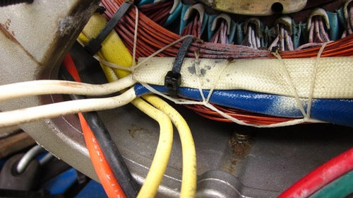
Devilbiss GB5000-2 generator rectifier wiring question
dwbdave
10 years ago
Related Stories
REMODELING GUIDESConsidering a Fixer-Upper? 15 Questions to Ask First
Learn about the hidden costs and treasures of older homes to avoid budget surprises and accidentally tossing valuable features
Full Story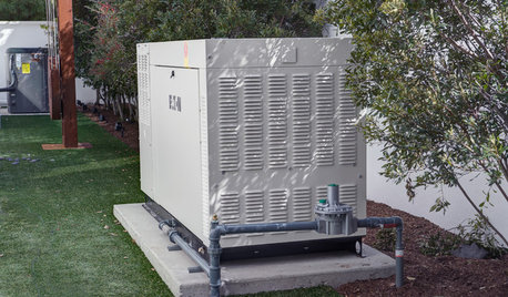
DISASTER PREP & RECOVERYMore Power to You: How to Pick the Right Generator
If your home's electricity goes, don't let it take your necessities with it — keep systems running with this guide to backup power
Full Story
MODERN HOMESHouzz TV: Seattle Family Almost Doubles Its Space Without Adding On
See how 2 work-from-home architects design and build an adaptable space for their family and business
Full Story
VINTAGE STYLEHouzz Tour: Farmhouse Meets Victorian in Los Angeles
Fanciful scrolls and sweet botanical prints join playful vintage touches for a home that’s altogether charming
Full Story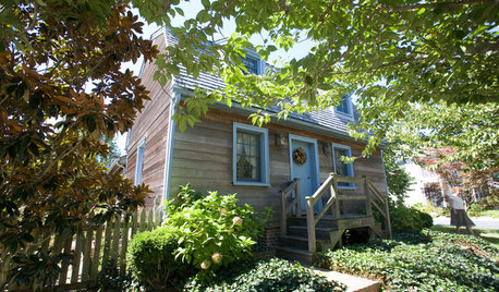
TRADITIONAL HOMESHouzz Tour: New Life for a Historic Mill House
Respectful reconstruction, an addition and a new site take a Delaware home from the 18th century to the present
Full Story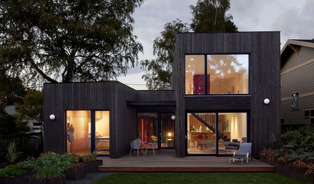
BASEMENTSDesign Workshop: Is It Time to Let Basements Become Extinct?
Costly and often unnecessary, basements may become obsolete — if they aren’t already. Here are responses to every reason to keep them around
Full Story
HOME TECHNew Strategies for Hiding the TV
Its easy to be discreet when you've got cabinets, panels and high-tech TV hiders like these
Full Story
GREEN BUILDINGOff the Grid: Ready to Pull the Plug on City Power?
What to consider if you want to stop relying on public utilities — or just have a more energy-efficient home
Full Story
CONCRETEWhy Concrete Wants to Crack
We look at the reasons concrete has a tendency to crack — and what you can do to help control it
Full Story
MOST POPULARShe’s Baaack! See a Savvy DIYer’s Dramatic $400 Bathroom Makeover
You’ve already seen her dramatic laundry room makeover. Now check out super budget remodeler Ronda Batchelor’s stunning bathroom update
Full Story
bus_driver
dwbdaveOriginal Author
Related Professionals
Banning General Contractors · Bowling Green General Contractors · DeRidder General Contractors · Evans General Contractors · Green Bay General Contractors · Saint George General Contractors · Spanaway General Contractors · Villa Park General Contractors · West Whittier-Los Nietos General Contractors · Little Ferry Solar Energy Systems · New Canaan Solar Energy Systems · Homer Glen Solar Energy Systems · Lewisville Home Automation & Home Media · Ocala Home Automation & Home Media · Wheaton Home Automation & Home MediadwbdaveOriginal Author
bus_driver
dwbdaveOriginal Author
brickeyee