


How To Connect 2 Ground Wires-1 Outlet?
Built new room on rear of house, knowledgeable friend did the wiring. Left the outlets/switches for me.
Wire is 12 ga. Romex, outlets are 20, amp. Hmmm, some of the single boxes have two wires--2 black, 2 white, and 2 bare grounds.
No problem with the power wires, each has its own screw. But there's only one ground screw, and no way can I get two 12 ga. wires around it.
So, do I twist the two bare wires together, leaving one longer to wrap the screw? Can't see any other way.
Comments (93)

mm11
11 years ago@ petey_racer
The minimum receptacle rating for a 20A branch circuit is only 15A (Table 210.24).
"...a receptacle shall not supply a total cord-and-plug load connected in excess of the maximum specified in Table 210.21(B)(2)." (210.21(B)(2)
The table shows that on a 20A circuit with 15A receptacles, the max load is only 12A.
However, a breaker on this circuit will not trip until the ampacity exceeds 20A.
If there was a 16A load at the end of the line, every 15A receptacle that was daisy chained by using the device terminals is carrying that load also. The rating on the device is now exceeded, which is a code violation and a safety hazard as well.
Is this a huge deal? Probably not, but using pigtails avoids potential problems. The current is not forced through every single receptacle upstream of the load, possibly exceeding the rating of the device. The current path can remain on conductors until it reaches the load.
Even if someone were to plug a 20A load into the end of the line receptacle of a pigtailed circuit, that load can be carried without possibly exceeding the ratings of the receptacles.
Series- one current path
Parallel- more than one current path
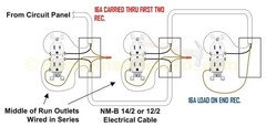
The receptacles (not the circuit) are wired in series below.
Ron Natalie
11 years agoActually VOLTAGE very much comes into it. Two basic truths about electricity:
1. Current going in has to equal current going out.
2. Some of voltages around the circuit has to add up to zero.A true series circuit has the same current through all devices, but each device has a voltage across it that is a share of the total voltage from the source. The sum of the voltages across each series device equals the source voltage.
Conversely, a true parallel circuit has the same voltage across all devices, but the totl current is divided between each parallel device.
Do not confuse AMPACITY (the rated amount of currrent the device can handle) and the CURRENT flowing.
Devices failure is unlikely, device removal is a more common item. There is NO tremendously COMPELLING reason on normal circuits to avoid making the current carrying connections through the device. On a MWBC, you indeed probably want to pigtail the grounded (neutral) connector, and finally
GETTING BACK TO THE ORIGINAL QUESTION:
You *MUST* pigtail the grounds using some approved connection method (wirenut, listed crimper, etc...). Putting two wires under the ground screw is NOT legal. Just twisting the grounds is not legal. Soldering, done right, is technically legal but a pain in the butt.
Related Professionals
Dorchester Center General Contractors · Euclid General Contractors · Hermitage General Contractors · Ken Caryl General Contractors · Kilgore General Contractors · Lighthouse Point General Contractors · North Smithfield General Contractors · Parkersburg General Contractors · Richfield General Contractors · Towson General Contractors · Van Buren General Contractors · West Melbourne General Contractors · Williamstown General Contractors · Delray Beach Home Automation & Home Media · Plainview Home Automation & Home Mediamm11
11 years ago@ greg_2010
The 4 or 5 failed receptacles I've come across are all at least 20+ years old. I did not disassemble and examine them, so I'm not sure what caused the failure. I did some testing, removed the old, pigtailed a splice, and installed a new device.
The failures are uncommon, but they do occur.
greg_2010
11 years agoSo can you describe the symptoms of the failure?
As you can see from the picture of the "receptacle ripped open" that you posted, there isn't much going on inside the receptacle. So it should be easy to figure out what the failure is based on the symptoms.
Breaker tripped?
Lost power downstream?
Appliance plugged in didn't work?
Any visible scorching?greg_2010
11 years agoAnd as I posted before, here are the 3 types of failures that I can think of:
(1) A short-circuit in the receptacle will affect both the daisy-chained configuration and the pigtailed configuration.
(2) A loose connection that is internal to the receptacle (so that anything plugged into it doesn't get a solid connection and won't work) will not affect electricity from passing through the screws/plate and on to the next receptacle.
(3) A loose connection at the screw terminal is exactly the same as a loose connection at your wire nut.
If you can think of any other types of failure based on your understanding of how electricity works, then please post it.
greg_2010
11 years agoAnd please take this in the 'tongue-in-cheek' manner that I'm meaning, and not the 'I'm insulting your intelligence' manner that it could be interpreted as.
Saying:
The daisy-chained device failed, I replaced it in the pig-tailing configuration, and everything is fine. The problem was the daisy-chaining. Don't ask any questions about why I think the daisy-chaining caused the problems.
Is like saying:
My car failed. I bought a new car and it works. The problem was the spark plugs. Don't ask any question about how I came to that conclusion, just trust me. Cars fail.
This post was edited by greg_2010 on Fri, Apr 5, 13 at 9:48
mm11
11 years agoCustomer called and says circuit not working.
Went to house to troubleshoot.
Checked breaker- still on.
Checked receptacles- no voltage past a certain receptacle. Everything downstream is off.
Took out problem device and tested. No voltage continuity.
Turned off circuit, replaced receptacle (using pigtails), and turned breaker back on.
Tested receptacles again- all have voltage now.
greg_2010
11 years agoTook out problem device and tested. No voltage continuity.
Can you please explain this further. You are saying that there was no continuity between one hot screw and the other hot screw?
That means that you should have been able to see that the plate (or bus or whatever you want to call it) was burned up and no longer existed. Is this the case?
mm11
11 years ago@ greg_2010
I said daisy-chaining receptacles is wiring them in series, which you mistakenly thought was incorrect.
We've examined current flow and voltage in a circuit, and I've shown how daisy-chaining receptacles puts the device itself in the circuit. When there is no cord and plug connected load to the device itself, the first receptacle in series carries all the ampacity of the circuit.
Once you finally figured out what wiring a device in series meant, here's your response.
"In your example 15 amps is on the bus of the first
receptacle. Who cares?It proves that the device is wired in SERIES.
I also gave some reasoning why daisy-chaining receptacles is not the best installation practice and backed that up with some code sections and examples.
Since you have no leg to stand on with the 'devices in series' concept, you've moved onto device failure as your new focus.
"My car failed. I bought a new car and it works. The problem was the spark plugs. Don't ask any question about how I came to that conclusion, just trust me. Cars fail."
To compare a 39 cent receptacle to a vehicle costing thousands of dollars is not a good comparison. Yes, I need to figure out why a circuit is not working. When I find that that path is broken and it's at the receptacle, the fix is to replace the device.
I wouldn't tell someone "Well you have a bad receptacle, and as a result you need a brand new service", which is closer to your comparison of the cost incurred with a new car.
mm11
11 years agoUsed my hot stick- tested line and load.
Line was hot.
Load was dead.
Therefore, no continuity of voltage.
mm11
11 years agoIt's not good time management to do an autopsy of failed devices. If there's no carbon build-up or visible signs of arcing, I throw it in the trash and continue with replacement.
greg_2010
11 years agoI'm not going back to discussing series vs parallel. I don't care about that discussion anymore. If you want to believe that you're right, go ahead.
Can we just continue along one discussion until we finish it? Instead of branching off in different directions?
I know that when you are in the field, it isn't worth the time to trouble-shoot some things. Just getting it working and moving on is important. However, we aren't in the field right now. We are having a discussion.
With your understanding of how electricity works, can you please explain how it is at all possible that two screws connected together by a plate are NOT continuous? Everything is visible to the naked eye. Something is apparently breaking the continuity. What? Where?
And I'm bringing the discussion back to device failure because that IS the discussion about why you are claiming that pigtailing is better than daisy-chaining.
This post was edited by greg_2010 on Fri, Apr 5, 13 at 11:04
Ron Natalie
11 years agoIf we're talking a non-MWBC, you are free to use the device terminals to daisy chain the current carrying wires onto the next device.
If we are talking a MWBC, you do not want to use the device to chain the grounded (that is neutral) conductor.
You can not use the single ground screw on a receptacle to connect more than one wire. For practical purposes, this means you have to pigtail the grounds using an APPROVED fastening method: wirenuts, crimps, properly executed soldering, etc but NOT just twisting.
mm11
11 years ago" Instead of branching off in different directions? "
That's really funny- lol. Seriously. I'm laughing :)
The reason you don't want go back to the daisy-chain discussion is you've been proven wrong.
Just because you don't understand something doesn't mean it's not correct.
There's lots of topics I choose not to comment on, because I'm not qualified to render an opinion- for example, interjecting into a discussion about plumbing. Just because I do some basic plumbing jobs at my home does not make me into a plumber.
Before you begin making assertions and trying very hard to back them up, make sure that you know the facts. If you don't understand, ask questions, instead of making up some new explanation of voltage and current flow in a circuit.
Now, to answer your question-
The best I can tell you is most likely the tab connecting the two terminals somehow stopped making contact. Maybe there was a lot of load applied over many years, and the metal became fatigued from expansion and contraction, and broke. Maybe there was a small short on a load connected to the receptacle, which blew apart the connection, thereby clearing the fault without the breaker tripping. These are just hypothesis- I show up after there's been an issue, not usually when the problem is happening.
greg_2010
11 years agoRon, you make me smile.
I appreciate the fact that this conversation has really gone off on a tangent that has nothing to do with the OPs original question. The fact that you keep trying to pull it back there is very noble.
I do apologize to everyone that is following this thread and getting annoyed. I just figured everyone else would have just written it off and moved on. I think that's what I'm going to do.
mm11, you've won. You wore me down. I'm not saying that you are right, just that you've won. I don't care anymore.
Take care everyone. Don't forget to spay and neuter your pets.
This post was edited by greg_2010 on Fri, Apr 5, 13 at 11:50
greg_2010
11 years agoOkay, I lied. I'm back, but I swear this is the last post. No really, this is the last one. :)
I posted my goodbye message at the same time as mm11, so I'd just like to make a quick response and be done.
BTW - That branching pun was actually unintentional. Made me smile when you pointed it out too.
In my opinion, the same types of failures in continuity that you just described are just as likely to happen in a wire nut. That is why I'm saying that pig-tailing and daisy-chaining are equally reliable.
Seacrest out.
mm11
11 years agoOkay, I'm back too.
Hopefully this has been an informative thread, and maybe even educational.
Greg_2010, thanks for the discussion and enjoy your weekend :)
Cheers, Mike
poobaloo
11 years ago"If there was a 16A load at the end of the line, every 15A receptacle that was daisy chained by using the device terminals is carrying that load also. The rating on the device is now exceeded, which is a code violation and a safety hazard as well"
If I'm not mistaken, a 15A receptacle is rated to carry 15A to the outlet but also 20A across the plate (pass through). Thus a 15A receptacle can be used inline on a 20A circuit without worry of 16A downstream going thru the plate on this outlet being a problem.
petey_racer
11 years ago"@ petey_racer
The minimum receptacle rating for a 20A branch circuit is only 15A (Table 210.24).
"...a receptacle shall not supply a total cord-and-plug load connected in excess of the maximum specified in Table 210.21(B)(2)." (210.21(B)(2)
The table shows that on a 20A circuit with 15A receptacles, the max load is only 12A.
However, a breaker on this circuit will not trip until the ampacity exceeds 20A. "
mm11, you ARE aware that a "15A" duplex receptacle is TWO 15A receptacles, aren't you???
You are describing them as if the whole device was rated for 15A.
EACH half of a 15A duplex receptacle is rated for an individual load not fastened in place of 12A.A 15A duplex receptacle IS RATED for 20A feed through. You are NOT exceeding the device rating if the device if 16A is passed through it, since the device is rated for 20A.
poobaloo
11 years ago"Another way to express the concept of voltage is the term electromotive force, or EMF. This is where the 'E' comes from in the Ohm's Law relationships- an example of which is E x I= R."
Huh? Ohm's law is V=IR. You're using E (EMF) to indicate V (Voltage) and saying E * I = R? That is completely wrong.
Think about that. That implies if you put in a bigger Resistor (R) on a circuit with a given voltage, you will have more current. Or if you remove all resistance (short it) then you'd have 0 current. Absolutely not. If you short a cirucuit your current would spike to the max your power supply could deliver!
Ohm's law is V=IR. That is, if Resistance goes up, Current goes down. If Resistance goes down, current goes up. Or, you can force more current by increasing the voltage potential.
I'm not an electrician... but I do have a physics degree... and I can tell you for 100% certain that Greg's assessment of cirucits, both in series and in parallel is correct.
mm11
11 years agoTypo on Ohm's Law. Sorry about that.
"I'm not an electrician... but I do have a physics degree... and I can tell you for 100% certain that Greg's assessment of cirucits, both in series and in parallel is correct. "
Not so at all.
This comes, back again, to the fact that the receptacle is physically installed as part of the circuit when daisy-chained connections are made.
The current enters the device on the line, goes across the bus of the device, and exits on the load side.
You used the term inline in an earlier post, which is exactly what occurs.
Example-
When using an in-line fuse as a supplemental overcurrent protective device with site lighting (pole lights), the hot conductor is interrupted and the fuse is installed in series in the base of the light, before the hot continues downstream to the load (the lamp). All the current flowing through this wire when the lamp's energized is also flowing through the fuse.
It's wired in series.
I'm no physicist, but I am an electrician :)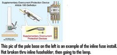
petey_racer
11 years agoA fuse is wired in series.
A lamp (or any other load) is NOT.It is STILL a parallel wiring circuit and NOT series.
mm11
11 years ago"mm11, you ARE aware that a "15A" duplex receptacle is TWO 15A receptacles, aren't you???
You are describing them as if the whole device was rated for 15A.
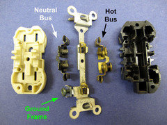
EACH half of a 15A duplex receptacle is rated for an individual load not fastened in place of 12A. "Refer to pic below.
If the device is listed at 15A, that means it's been found suitable for use at that ampacity.
The whole device. Not parts- when current flows across the bus, it doesn't partition itself.
Imagine 3 separate, non-concurrent loads on a circuit.
-10A load on half of a duplex, and 2A load on the other half
-12A load on one half
-12A load on the other half
They all represent the same load to the system. The allowable ampacities are not exceeded, and the load was pulling 1440W through the device. It doesn't matter which contact needs more current, because the bus carries all the current flowing through the device.
mm11
11 years agoI never said that any receptacle circuit is series, or the circuit in the pole light example I gave.
Please- try to follow along
For purposes of WIRING, physically installing a inline fuseholder and daisy-chaining a receptacle using the terminal screws are the same exact thing.
They serve different purposes in the circuit, and their intent is different, but...
The current flows through the fuse- it has to, because the hot is wired in series.
The current flows through the receptacle, even with no cord/load connected at that particular receptacle- it has to, because the hot is wired in series.
Just because the circuit is parallel, doesn't mean that parts of it aren't series.
Leaving the panel- the hot is in series, because all the current on that circuit must flow through the OCPD. Would you try want to have a parallel hot at that point? No, because the branch (hot) that bypassed the OCPD wouldn't be protected.
poobaloo
11 years agomm,
It doesn't matter, at all, what physical mediums are involved. You could solder two bits of wire to a fork and complete the circuit. That's the part you don't seem to be following. It doesn't matter that the power going to a downstream load is passing thru a busbar on a device. That particular bit of copper is used as part of the circuit just like every other bit of copper in the wires.As Greg described (eloquently) "In series" and "In parallel" describe the path power takes when flowing to loads.
Serial is rarely, if ever, done. I can think of scant few examples of it in the real world. One that comes to mind is cheapo Christmas lights. You unplug one bulb and the 20 others in series go out. Another is when you want to use car speakers (4 ohm) in a household stereo (8 ohm)... Speaker guru's would take two car speakers and wire them in series... (into one speaker on the black tab, out the red tab, then directly to the black tab of the next, then out the red tab and back to the stereo). Wiring them in series like this combines their resistance, since the sound has to flow thru both speakers.
Serial: Power flows thru black wire, into a load (something that creates resistance - like a bulb, motor, TV, toaster), then passes out the device... then passes into another load then out of that load and back to the neutral in the panel.
Parallel: Power flows thru any number of mediums, and at some, any, or all of them, it may branch... going to one load, then out that load and back to the neutral and back to the panel... Or going to a different load, then out that and hooking up to the neutral.
Serial: Every electron flowing passes thru BOTH devices. It travels into one device, then out, then into the other, then out, then back home.
Parallel: Any one given electron is either flowing thru load 1 OR load 2. If there are a million electrons flowing, half are going thru load 1 and half thru load 2 ("half" being used loosely, since it may be more or less than half pending the resistance of each load).
Home wiring is not in any way Serial.
Even the "fuse example" is a shaky one, since a fuse is not a load. It is nothing more than an inline part of the circuit that will break if the current exceeds a certain amount. At no point is the fuse considered a "load" and so it is technically not even "in series" it's just a part of the circuit. It's an inline fuse.
mm11
11 years ago"Home wiring is not in any way Serial."
I hate to burst your bubble here, but all circuits originating from a panel (even your home panel) are a combination of series and parallel current flow.
Service comes into the panel. This is a parallel circuit. There are multiple branches for current.
A 20A breaker has a load begin, and the current flows through the OCPD on the hot wire. The hot wire has to be in series here, or it would bypass the OCPD.
As the current goes downstream, it has multiple branches to choose from; it goes where it is needed. This portion has the current flow in parallel.
"Even the "fuse example" is a shaky one, since a fuse is not a load. It is nothing more than an inline part of the circuit that will break if the current exceeds a certain amount. At no point is the fuse considered a "load" and so it is technically not even "in series" it's just a part of the circuit. It's an inline fuse."
You seem to miss the point of my example. The inline fuseholder and the daisy-chained receptacle use the hot wire in the same way- it's broken, taken across the equipment/device, and continues downline. The current flow through the hot wire is in series.
Series current flow- only one path
Parallel current flow- more than one path
brickeyee
11 years agoThat is not exactly how it is usually described.
Leaving the source the current is in summation.
poobaloo
11 years agoWow.
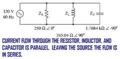
*** "Leaving the source the flow is in series".
No, it is not. Current is only flowing thru loads in series if it flows thru two or more loads before returning to the power source. In that diagram, the current could flow thru Zr, Zl, or create a potential across Zc. There is absolutely no current in that diagram that will go thru 2 or 3 of those loads.
*** "A 20A breaker has a load begin, and the current flows through the OCPD on the hot wire. The hot wire has to be in series here, or it would bypass the OCPD."
No. The OCPD is not "in series" because it is not drawing power. Only a load draws power. The OCPD measures the power flowing thru it, but it does not consume power. The OCPD is merely an inline element of the circuit. Like the "fork" in the above example. You can prove that your OCPD is not drawing power by putting your voltmeter from the screw of the OCPD to the hot bar in the panel. You'll see 0 voltage there. Because it is simply a non-resistive conductor, not a load.
If the OCPD actually drew power, it would be in series - but that would be disastrous!!! Let's say you buy a light-up Christmas breaker that has bulbs and plays music and consumes power. Do you realize then that the rest of the devices "in series" as you're putting it, would get an incorrect voltage?
Voltage among loads in series is additive / deductive. That is, if you hooked up two toasters (let's call them identical to save on the math) then instead of each getting 120V, each would get only 60V! This would trash your voltage sensitive equipment.
*** "You seem to miss the point of my example. The inline fuseholder and the daisy-chained receptacle use the hot wire in the same way- it's broken, taken across the equipment/device, and continues downline. The current flow through the hot wire is in series."
No it's not. The current flow is simply "thru the hot wire, thru the bus bar, thru another wire, thru a fuse, thru more wire, thru a fork, and thru more wire". Nowhere in there is there a load that creates resistance. The fork, fuse, and busbar are not "in series" they are merely a conducting part of the circuit.
Series / Parallel ONLY describes the paths thru loads. Not the paths thru the conductors making the circuit itself.
poobaloo
11 years agoI think I understand where you're going wrong. You seem to think that in that diagram, where the electricity comes out of the power supply and is all flowing thru the same wire... but before it branches... for that short while, it was in series. That is not what "in series" is. You seem to think it is that -- but it's not.
It is only in series if it actually goes thru two resisting loads in series (whether they be resistors, inductors, capacitors, motors, lights, etc doesn't matter). If you added two loads on that leg -- then at that point those two loads are connected in Series. Like ZR1 and ZR2 in this image are in Series. In fact, ZR1 and ZR2 and a "virtual combination of the 3 devices in Parallel"... are all in series...
That is,
All the current will flow thru ZR1
All the current will flow thru ZR2
All the current will flow thru one part of ZR3, ZL, and ZC (tho some will go thru ZR3, some thru ZL and some thru ZC, the total current going thru those 3 will be "all" of the current).Problem w this is that it would never work in a home because you're going to have voltages that vary depending on the resistances of the varisous loads indicated there. It would be a crazy mess. We could do the math if you were interested and assign some typical "devices" to each resistor. :-/

brickeyee
11 years ago'Series' and 'parallel' generally refer to loads, not wires.
The only time they refers to wires is the special case of paralleling smaller wires to create a larger current carryig capacity.
A practice prohibited for smaller wires, and even with larger conductors it must be done VERY carefully to ensure equal load sharing based on impedance in the circuit.
Simple resistance does not work all that well for equal current sharing, especially for large currents.Even the magnetic fields around the wires can interact to limit perfect sharing.
Running a circuit (hot, neutral, groundING) from one outlet to another is often referred to as 'daisy chaining' to eliminate the idea of the outlets being 'in series.'
It is like the slack habit of calling the two 120 V legs 'phases.'
They are NOT.
It is an 'Edison circuit' or 'single phase, center tapped' system.
It has the distinct advantage of allowing 240 V for large loads, while never having either conductor be more than 120 V to ground (groundED or groundING conductor).
w0lley32
11 years agoIn a series circuit the current is the same throughout the circuit and the voltage is function of each independant load present.
In a parallel circuit the voltage is the same throughout the circuit and the current is function of each independant load present.
Therefore if you can plug a 10 amp toaster in receptacle A and a 2 amp mixer in receptacle B and then measure 12 amps between receptacle A and the source, and 2 amps between receptacles A and B, your circuit has no other choice but to be wired in parallel. The voltage measured would be close to 120 volts throughout.
mm11
11 years ago@ brickeyee-
"The only time they refers to wires is the special case of paralleling smaller wires to create a larger current carryig capacity."
What about a shunt-trip breaker, where there is an added path (wire) to trip the circuit?
It's often been my experience to use parallel feeders to a piece of gear- not really a special case, but I understand what you meant.
mm11
11 years agoMaybe this thread from Mike Holt's will help explain my position.
Some of the posters are for pigtails, some think it's a waste of time.
All seem to be against using the backstab port on the receptacle (for #14 Cu).
There also is an understanding that when the circuit depends on the receptacle itself to continue the circuit downline, meaning daisy-chained through the device, when the connection/device fails, everything downline fails also.
Parallel circuit wiring, receptacles daisy-chained in series.
Here is a link that might be useful: Mike Holt's Forum
Ron Natalie
11 years agoAs pointed out earlier, I've never seen a receptacle FAIL such as to lose the downstream connections. I've seen them physically damaged so that it's not safe/possible to use, but not in a way that lost electrical continuity between the terminals. I've seen plenty of poorly installed things that the connections have come open, but that's not going to be something that is more or less likely to happen based on using either a device or a pigtail.
The code and real safety concern is not device failure but device removal. Normally, opening the current carrying wires just makes things not work (safely). The two things you don't want to risk connection failures are on the equipment ground and a shared neutral in a MWBC situation. In those situations, you never want the device to be part of the connection.
Otherwise, it's a matter of personal choice and electrical folklore.
petey_racer
11 years agoSorry mm11, you are 1000% wrong on this. Both topics as well.
If a 15A receptacle is EXPRESSLY allowed on a 20A circuit, WHY would it only be rated for 15A feed-thru??? Because it is NOT.
In fact, if you ever looked at a 15A GFI device is SPECIFICALLY says "20A feed through". Would you like a picture of one. I'm not sure if you deal with GFI's much.brickeyee
11 years ago"It's often been my experience to use parallel feeders to a piece of gear- not really a special case, but I understand what you meant. "
Having separate feeders to gear is still not the same as paralleling conductors for increased ampacity.
Large pieces of equipment may have multiple feeders to different sections, but are not generally referred to as parallel.
I have installed many large pieces of gear that have separate feeders for large motor loads, often at much higher voltages an 3-phase, while still having lower voltage feeders for the computerized control systems.
And then using even lower voltage power limited circuits for remote control and monitoring of the whole thing
(let alone the video links, LAN links, etc.).Every once in a while some PC guy wants to know why we do not use wireless.
I hook a spectrum analyzer up to an antenna that is now permanently mounted in the equipment bay and show him the RF noise levels in the area.
It is a good thing we have concrete walls or we would be a jammer in the RF world.
Cell phones do not even work inside our building (between the building attenuation and the EMI).
It does make the 'no cell phones' rule easy to enforce.
This post was edited by brickeyee on Sat, Apr 6, 13 at 10:11
hexus
11 years agoit's awesome how a simple question on how to use crimp sleeves to connect grounds together, turned into this craptastic thread full of wrong information.
benesesso
Original Author11 years agoDeleted.
This post was edited by benesesso on Mon, Apr 8, 13 at 17:10
mm11
11 years ago@petey_racer
Thanks for the offer of a picture, but I'm familiar with GFCIs. I looked up the UL standard 'RTRT' for receptacles and I stand corrected. The 15A receptacle is rated for 20A pass-through.
@brickeyee
To clarify, I meant parallel feeder conductors- for example, (3) 600kcmils per phase.
@squishyball
"Series / Parallel ONLY describes the paths thru loads. Not the paths thru the conductors making the circuit itself."
Not correct.
Here's another example of a parallel circuit, with current flow in series through the conductors.
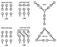
When wiring a dual-voltage motor (460/230V), the windings of the motor are physically wired in series or parallel. For the higher voltage, the windings (conductors) are connected in series.
The motor uses a parallel circuit, yet the current on each phase has only one path; the path through the conductors is in series.
FYI, many textbooks also use the same terminology- motors wired in parallel for low voltage operation, wired in series for high voltage operation.

mm11
11 years agoHere's another wiring diagram, showing delta and wye configurations.
High voltage wired in series, low voltage wired in parallel.
brickeyee
11 years agoThis is a common 'trick' for large loads like motors.
By bringing out more of the motor windings from the stator the device can be used at more than one operating voltage.
It increases the complexity of the windings though since they must be divided into appropriate sections and then the terminals made available.The same thing s done with motors designed for 120/240 V operation (not "high voltage" at all).
It has littler to do with branch circuit wiring topology.
You will notice we do not have 120 V bulbs and 60 V bulbs.
This is what would be required to have some portion of alighting circuit in series and some portion in parallel.
I personally do not do production wiring and use crimps for much at all.
You will learn to dislike them when you start doing remodeling work and are no longer doing all 'new work'.I do charge extra when I am forced to deal with remodeling that has crimp connections.
Simply cutting them off is often not an option since the remaining conductor length often then violates the minimum length required from the face of the junction box.I am sure it speeds up the 'production' installers though.
Right now I have a house with a built in on one side of a wall, and a tile backsplash on the other in a kitchen.
I need a couple new circuits for under-cabinet lighting.
It looks like I will have to go through the back of the kitchen cabinets and fish upwards to the new junction boxes in the back of the upper cabinets.At least there are no crimps present in the boxes already containing some lighting switches.
poobaloo
11 years agomm11,
You've now moved on to using other definitions of the word "series".Yes "series" has many meanings.
10 ornaments on a string could be described as "in series".
The numbers 2, 4, 6, 8, 10... could be described as a series.
A group of 7 games in a row could be called a series.However you used "series" as in to describe the topology of a circuit that may be series or parallel... Your original statement was:
"When receptacles are wired like this (series)"
Those receptacles are not wired in series. They are wired in parallel.
The fact that the bus bar is being used to complete the circuit and that if you take out the receptacle it breaks the circuit does not make it series.
Yes you can go down any tangent you want and describe any number of other ways to use the phrase "in series"...
but those receptacles are still hooked up in parallel.
The presence (or not) of a 6" pigtail does not change the topology of the circuit from serial to parallel.
Here's a good one for you. :-) What if the device came with affixed pigtails... like some switches do... Now, to connect to that, you pigtail your two hots to the hot lead of the device... is that device in serial or parallel to you? A) it uses a pigtail... but B) if you remove the device, you must undo the wirenut thereby breaking the circuit. It would create a paradox by your definition, but is still parallel all the way just like all the other hookups of 120v household outlets.
mm11
11 years ago"It has littler to do with branch circuit wiring topology. "
The concept is the same however- only one path for current flow.
I posted the motor info to show that parts of a parallel circuit can contain series current flow, since I was met with such disbelief that current could ever be in series in a branch circuit.We are not required to crimp here- it definitely looks like it would be a pain to deal with for old work.
mm11
11 years ago@squishyball
"The fact that the bus bar is being used to complete the circuit and that if you take out the receptacle it breaks the circuit does not make it series.
Yes you can go down any tangent you want and describe any number of other ways to use the phrase "in series"...
but those receptacles are still hooked up in parallel."
I've not changed my definition of series.
Look back at my previous posts.
Series- only one path for current to flow.
I never wrote that any CIRCUIT is series, only current flow through through the conductors.
Daisy-chaining receptacles means the devices are connected in series
The NEC specifically recognizes this in 300.13 (B).
"In multiwire branch circuits, the continuity of a grounded conductor shall not depend on device connections such as lampholders, receptacles, and so forth, where the removal of such devices would interrupt the continuity."

This post was edited by mm11 on Mon, Apr 8, 13 at 12:11
poobaloo
11 years agoThat diagram does not say those outlets are hooked up in series! It just says that in an MWBC the neutral must be pigtailed -- which makes perfect sense. You've shown an unrelated image about some other topic and claim that makes your point? It makes no comment at all about that being a series or parallel circuit. There are two circuits depicted in that diagram. The black circuit and the red. Notice the black circuit goes thru the first outlet before going to the 2nd outlet or the top outlet... Even tho the black/red are daisychained but the white is pigtailed, those are ALL devices hooked up in parallel. You will get 120V at each and every one of them. If any of them were hooked up in series, your voltages would be additive - not constant.
"Series- only one path for current to flow."
Ok... and in the case of two receptacles being daisy chained, there are TWO paths to flow.
A) source wire to bus bar to device plugged in to bus bar to other bus bar to neutral, or...
B) source wire to bus bar to another wire to another bus bar to a device plugged into that outlet to neutral bus bar to neutral wire to the first neutral bus bar to the home neutral.
There are 2 paths when daisychainging 2 receptacles. (technically there are 4 paths since each duplex has two outlets).
Yes, removing a device can interrupt a parallel circuit. Just as removing any other element like a piece of wire or a wirenut.
This post was edited by squishyball on Mon, Apr 8, 13 at 12:38
mm11
11 years ago"Ok... and in the case of two receptacles being daisy chained, there are TWO paths to flow.
A) source wire to bus bar to device plugged in to bus bar to other bus bar to neutral, or..."
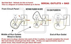
Except when there's nothing plugged into that receptacle, like the example below, where the first 2 receptacles are carrying the load downstream.

poobaloo
11 years ago'Except when there's nothing plugged into that receptacle'
If there are only 2 outlets, and only something plugged in to 1 of them, then you are talking about a single load. A single load is neither parallel nor serial. Parallel and Serial describe how power flows to loads in relation to each other.
Serial... All the current flows thru each load in series. First thru one, then thru another. (not thru a busbar, but thru the actual load)
Parallel... Some of the current flows thru one load and some thru another. All house wiring is like this.
If you are using an example of 'yes but if there is only 1 load' then you just are not getting what Serial and Parallel mean.
It would be like drawing a picture and asking 'Are the two red boxes here near or far from each other?' but if the picture contains only 1 red box, then the question is clearly meaningless.
This is serial. Note the power flows COMPLETELY THRU each outlet - not just the bus bar. Unplugging a device/load from any of the 3 circuits would break the circuit.
poobaloo
11 years agomm11,
You're obviously not the only one to have thought this before. See here. Same exact discussion. All outlets are hooked up in parallel and the method of physical connection (wirenut & pigtail vs backwire) does not change the circuit topology.Don't know what else to tell ya on it.
-mikeHere is a link that might be useful: Same discussion 3 yrs ago


hendricus