


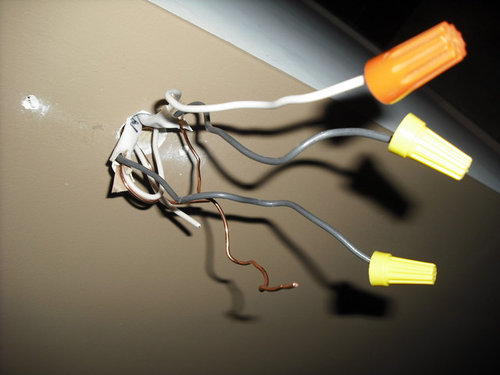
Need Wiring Help to Install Overhead Light Garage Sensor
Syd.1
11 years ago
Related Stories

DREAM SPACESDesign Workshop: The Case for Big Overhead Doors
Garage-style doors are cost-effective solutions for opening rooms to dream views and fresh air — and they’re more stylish than ever
Full Story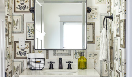
BATHROOM DESIGNKey Measurements to Help You Design a Powder Room
Clearances, codes and coordination are critical in small spaces such as a powder room. Here’s what you should know
Full Story
KITCHEN DESIGNKey Measurements to Help You Design Your Kitchen
Get the ideal kitchen setup by understanding spatial relationships, building dimensions and work zones
Full Story
DECORATING GUIDESDecorate With Intention: Helping Your TV Blend In
Somewhere between hiding the tube in a cabinet and letting it rule the room are these 11 creative solutions
Full Story
SMALL SPACESDownsizing Help: Storage Solutions for Small Spaces
Look under, over and inside to find places for everything you need to keep
Full Story
GREAT HOME PROJECTSLight Your Landscape for Drama and Function
New project for a new year: Install outdoor lighting to highlight special features and keep nighttime walks safe
Full Story
REMODELING GUIDESWisdom to Help Your Relationship Survive a Remodel
Spend less time patching up partnerships and more time spackling and sanding with this insight from a Houzz remodeling survey
Full Story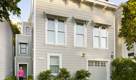
LIFE12 House-Hunting Tips to Help You Make the Right Choice
Stay organized and focused on your quest for a new home, to make the search easier and avoid surprises later
Full Story
SELLING YOUR HOUSE5 Savvy Fixes to Help Your Home Sell
Get the maximum return on your spruce-up dollars by putting your money in the areas buyers care most about
Full Story
SELLING YOUR HOUSE10 Low-Cost Tweaks to Help Your Home Sell
Put these inexpensive but invaluable fixes on your to-do list before you put your home on the market
Full StoryMore Discussions
jeepdrvr101
Syd.1Original Author
Syd.1Original Author
brickeyee
Syd.1Original Author
Syd.1Original Author