


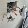
4 wires for 240v appliance
Rocky865
12 years ago
Related Stories
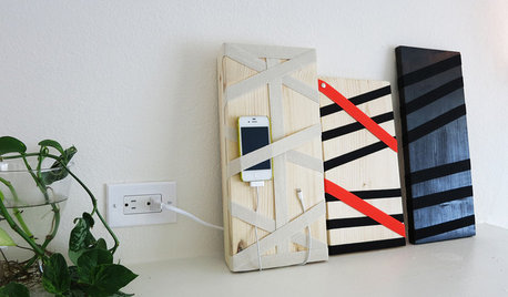
DIY PROJECTSHide All Those Wires in a DIY Charging Station
Keep your gadgets handy and charged with a flexible storage board you can design yourself
Full Story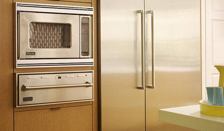
KITCHEN DESIGNA Cook’s 6 Tips for Buying Kitchen Appliances
An avid home chef answers tricky questions about choosing the right oven, stovetop, vent hood and more
Full Story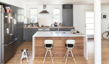
KITCHEN DESIGNNew This Week: 4 Subtle Design Ideas With Big Impact for Your Kitchen
You’ve got the cabinets, countertops and appliances in order. Now look for something to make your space truly stand out
Full Story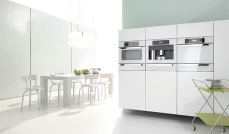
KITCHEN DESIGNWhite Appliances Find the Limelight
White is becoming a clear star across a broad range of kitchen styles and with all manner of appliances
Full Story
MORE ROOMSOn Trend: Smart Solutions for Cords
Show those cables and wires who's boss with these clever solutions for the home office
Full Story
TASTEMAKERSPro Chefs Dish on Kitchens: Michael Symon Shares His Tastes
What does an Iron Chef go for in kitchen layout, appliances and lighting? Find out here
Full Story
FARM YOUR YARDGrow a Kitchen Garden in 16 Square Feet
Got a sunny 4-by-4 space? You can make meals more interesting with your own vegetables and herbs
Full Story
KITCHEN DESIGNNew This Week: 4 Ways to Punch Up a White Kitchen
Avoid the hospital look by introducing a bit of color, personality and contrast
Full Story
KITCHEN DESIGNThe 4 Things Home Buyers Really Want in Kitchen Cabinetry
For the biggest return on your kitchen investment, you've got to know these key ingredients for cabinetry with wide appeal
Full Story
MOST POPULAR4 Obstacles to Decluttering — and How to Beat Them
Letting go can be hard, but it puts you more in control of your home's stuff and style. See if any of these notions are holding you back
Full StoryMore Discussions
dkenny
ionized_gw
Related Professionals
Hainesport General Contractors · Amarillo General Contractors · East Riverdale General Contractors · Fort Lee General Contractors · Lakewood Park General Contractors · Lighthouse Point General Contractors · Pocatello General Contractors · Rohnert Park General Contractors · Sterling General Contractors · Waipahu General Contractors · Laurel Home Automation & Home Media · New York City Home Automation & Home Media · Phoenix Home Automation & Home Media · Tampa Home Automation & Home Media · Wheaton Home Automation & Home Mediabus_driver
brickeyee
Rocky865Original Author
Rocky865Original Author
bus_driver
brickeyee