
Need help with Pressure Regulator (see picture)
thomas_e
11 years ago
Sort by:Oldest
Comments (9)
Related Stories
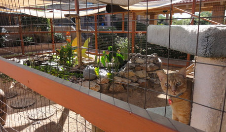
PETSSee a Deluxe 'Catio' Built for Feline Fun
Sixteen lucky cats get the run of a protected outdoor patio with ramps, steps and even a koi pond
Full Story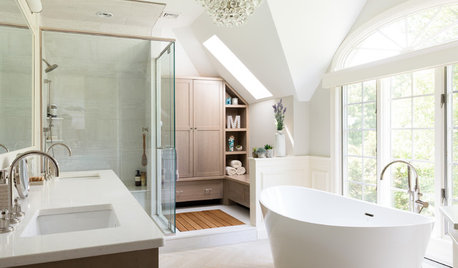
BATHROOM WORKBOOKStandard Fixture Dimensions and Measurements for a Primary Bath
Create a luxe bathroom that functions well with these key measurements and layout tips
Full Story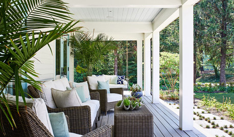
STANDARD MEASUREMENTSThe Right Dimensions for Your Porch
Depth, width, proportion and detailing all contribute to the comfort and functionality of this transitional space
Full Story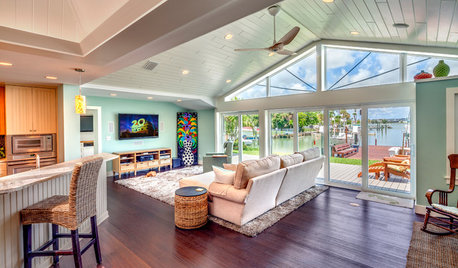
REMODELING GUIDESCoastal Makeover: A Florida Home Sees the Light
They're done! Check out the result of a ranch home that went from dark and dated to bright and airy — with a coveted water view
Full Story
HOME TECHGadgets Help You Watch Your Health at Home
See the crop of new devices that can monitor your body's vital signs and environment for health, fitness and fun
Full Story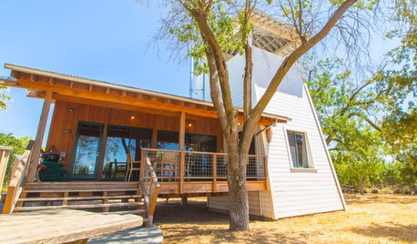
HOUZZ TOURSHouzz TV: See a Modern Family Farmhouse That Can Pick Up and Move
In the latest episode of Houzz TV, watch California architect build a beautifully practical cabin to jumpstart his parents' new farm
Full Story
FLOORSHow to Get a Tile Floor Installed
Inventive options and durability make tile a good choice for floors. Here’s what to expect
Full Story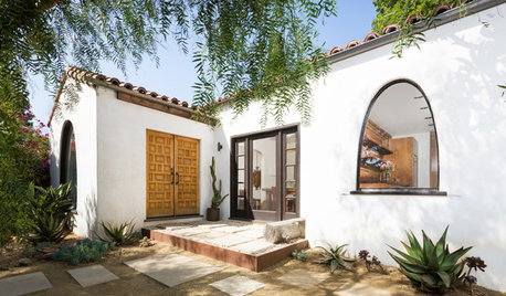
BEFORE AND AFTERSHouzz TV: See Recycled Walls and Cool Cassette Art in a Woodsy DIY Home
Walnut countertops join hardwood floors and pieces made from leftover framing in a bright Spanish colonial
Full Story
BEFORE AND AFTERSSee 6 Yards Transformed by Losing Their Lawns
Wondering whether a turf lawn is the best use of your outdoor space? These homeowners did, and they found creative alternatives
Full Story
EXTERIORSHelp! What Color Should I Paint My House Exterior?
Real homeowners get real help in choosing paint palettes. Bonus: 3 tips for everyone on picking exterior colors
Full StoryMore Discussions

lazypup
thomas_eOriginal Author
Related Professionals
Andover Kitchen & Bathroom Remodelers · Blasdell Kitchen & Bathroom Remodelers · Buffalo Grove Kitchen & Bathroom Remodelers · Dearborn Kitchen & Bathroom Remodelers · Mesquite Kitchen & Bathroom Remodelers · Payson Kitchen & Bathroom Remodelers · Tempe Kitchen & Bathroom Remodelers · Vancouver Kitchen & Bathroom Remodelers · Vashon Kitchen & Bathroom Remodelers · Vista Kitchen & Bathroom Remodelers · Shaker Heights Kitchen & Bathroom Remodelers · North Chicago Kitchen & Bathroom Remodelers · Glenn Heights Kitchen & Bathroom Remodelers · Ridgefield Park Kitchen & Bathroom Remodelers · Kiryas Joel Applianceslazypup
thomas_eOriginal Author
thomas_eOriginal Author
thomas_eOriginal Author
thomas_eOriginal Author
thomas_eOriginal Author
woodbutcher_ca