


electrical needs for tankless water heater
hdclown
15 years ago
Featured Answer
Comments (11)

bus_driver
15 years agoRelated Professionals
Franklin Plumbers · Livingston Handyman · North Druid Hills Kitchen & Bathroom Remodelers · Bloomingdale Kitchen & Bathroom Remodelers · Dearborn Kitchen & Bathroom Remodelers · Deerfield Beach Kitchen & Bathroom Remodelers · Eagle Kitchen & Bathroom Remodelers · Ewa Beach Kitchen & Bathroom Remodelers · Glen Carbon Kitchen & Bathroom Remodelers · Overland Park Kitchen & Bathroom Remodelers · South Lake Tahoe Kitchen & Bathroom Remodelers · Southampton Kitchen & Bathroom Remodelers · Vienna Kitchen & Bathroom Remodelers · Vista Kitchen & Bathroom Remodelers · South Jordan Kitchen & Bathroom Remodelersjoed
15 years agohdclown
15 years agojake2007
15 years agohdclown
15 years agobus_driver
15 years agojake2007
15 years agohdclown
15 years agojakethewonderdog
15 years agobus_driver
15 years ago
Related Stories
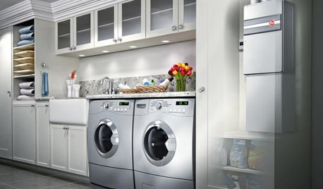
GREAT HOME PROJECTSHow to Switch to a Tankless Water Heater
New project for a new year: Swap your conventional heater for an energy-saving model — and don’t be fooled by misinformation
Full Story
GREAT HOME PROJECTSHow to Add a Solar Water Heater
Lower energy bills without a major renovation by putting the sun to work heating your home’s water
Full Story
REMODELING GUIDESGet What You Need From the House You Have
6 ways to rethink your house and get that extra living space you need now
Full Story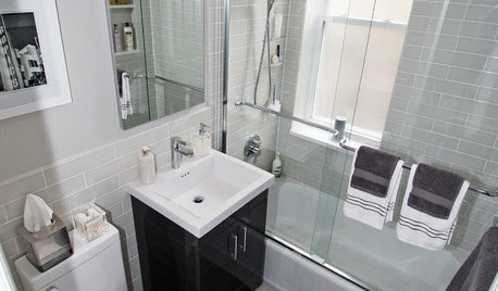
BATHROOM DESIGNWater Damage Spawns a Space-Saving Bathroom Remodel
A game of inches saved this small New York City bathroom from becoming too cramped and limited
Full Story
KITCHEN APPLIANCESLove to Cook? You Need a Fan. Find the Right Kind for You
Don't send budget dollars up in smoke when you need new kitchen ventilation. Here are 9 top types to consider
Full Story
ARCHITECTUREDo You Really Need That Hallway?
Get more living room by rethinking the space you devote to simply getting around the house
Full Story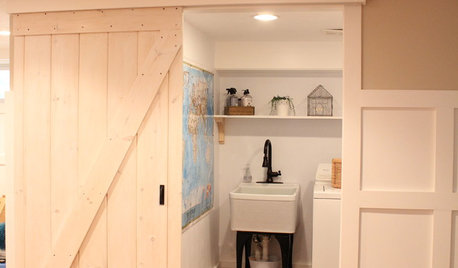
DIY PROJECTSMake Your Own Barn-Style Door — in Any Size You Need
Low ceilings or odd-size doorways are no problem when you fashion a barn door from exterior siding and a closet track
Full Story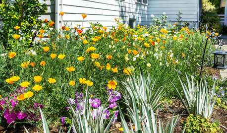
LANDSCAPE DESIGN10 Ideas for a Creative, Water-Conscious Yard
Check out these tips for a great-looking outdoor area that needs less water
Full Story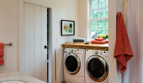
GREEN BUILDINGWater Sense for Big Savings
Keep dollars in your pocket and preserve a precious resource with these easy DIY strategies
Full Story
SAVING WATER11 Ways to Save Water at Home
Whether you live in a drought-stricken area or just want to help preserve a precious resource, here are things you can do to use less water
Full Story
jake2007