


mini split power observations
ionized_gw
9 years ago
Sort by:Oldest
Comments (5)
Related Stories
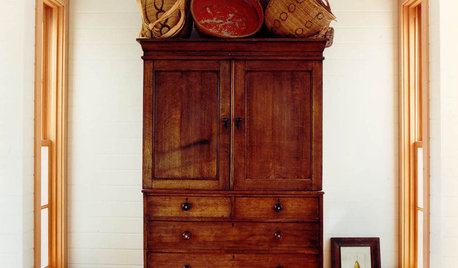
DECORATING GUIDESA Beginner's Mini Guide to Buying Antiques
Experience the thrill of the hunt without ignorance ruining the spoils, with this guide to antiquing for novice buyers
Full Story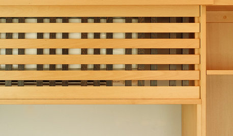
DECORATING GUIDES10 Ways to Hide That Air Conditioner
Feeling boxed in designing around your mini-split air conditioner? Try one of these clever disguises and distractions
Full Story
ARCHITECTUREWhat's Next for Our Homes' Exterior Design?
Take a mini tour of architecture's changing response to basic needs, throughout history and going forward
Full Story
LIFE10 Things Night Owls Know to Be True
Love being up while the world slumbers? Prefer a really late bedtime to an early night? These observations on night owl life may ring true
Full Story
LIFEYou Said It: ‘It’s Important to Wait’ and More Houzz Quotables
Design advice, inspiration and observations that struck a chord this week
Full Story
LIFEYou Said It: ‘What Do You Want Your Deck to Do?’ and More Quotables
Design advice, inspiration and observations that struck a chord this week
Full Story
You Said It: ‘The More Dents, the Better’ and More Houzz Quotables
Design advice, inspiration and observations that struck a chord this week
Full Story
COMMUNITYLittle Free Libraries Take Manhattan
Designers' modern mini libraries boost reading and community in New York City
Full Story
FIREPLACESUpdated Woodstoves Keep Home Fires Burning
Better technology means more efficiency than ever for modern woodstoves
Full Story
REMODELING GUIDESArchitect's Toolbox: Bridges That Unite Home and Land
Spanning an abyss or meant for a meditative meander, bridges on home sites inspire awe and wonder
Full StoryMore Discussions

fsq4cw
ionized_gwOriginal Author
Related Professionals
Bell Gardens Solar Energy Systems · Elmwood Park Solar Energy Systems · Fontana Solar Energy Systems · Frankfort Solar Energy Systems · Lomita Solar Energy Systems · Weymouth Solar Energy Systems · Azalea Park Solar Energy Systems · Alexandria Home Automation & Home Media · Orlando Home Automation & Home Media · Saint Augustine Home Automation & Home Media · Weatherford Home Automation & Home Media · East Cleveland Home Automation & Home Media · Evans Fireplaces · Hoffman Estates Fireplaces · North Ogden Fireplacesfsq4cw
weedmeister
ionized_gwOriginal Author