


Improve an FM antenna?
bluewhale
19 years ago
Related Stories
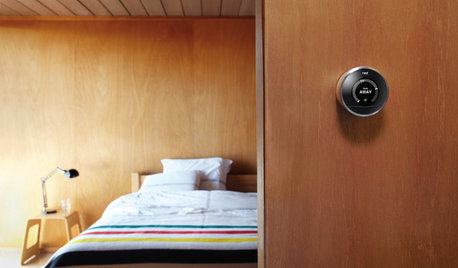
ACCESSORIESEveryday Home Must-Haves Beg for a Makeover
The Nest's much-improved take on the thermostat has us pondering reinventions of other necessities around the house
Full Story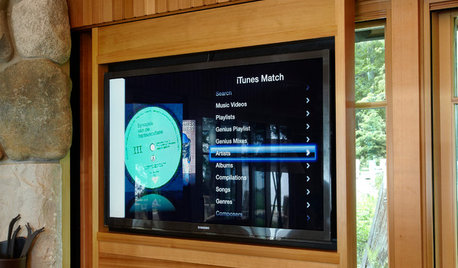
HOME TECHNew Strategies for Hiding the TV
Its easy to be discreet when you've got cabinets, panels and high-tech TV hiders like these
Full Story
HOME TECHTote Your Tunes to Any Room With a Portable Wi-Fi Sound System
Free your home's music setup from wires with Wi-Fi speakers that let you take high-quality audio anywhere
Full Story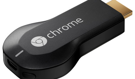
HOME TECHNow Playing in Homes Everywhere: TV, the App
It's easier than ever to beam streaming content from mobile devices to your TV screen
Full Story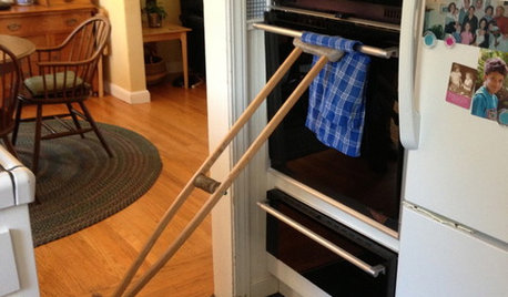
LIFEYou Showed Us: 20 Nutty Home Fixes
We made the call for your Band-Aid solutions around the house, and you delivered. Here's how you are making what's broken work again
Full Story
GARDENING GUIDESBackyard Birds: Invite Entertaining Hummingbirds Into Your Garden
Hummingbirds — unique to the Americas — zip through open landscapes seasonally or year-round. Here’s how to attract them
Full Story
SMALL HOMESAsk an Expert: What Is Your Ultimate Space-Saving Trick?
Houzz professionals share their secrets for getting more from any space, small or large
Full Story
REMODELING GUIDESPocket Doors and Sliding Walls for a More Flexible Space
Large sliding doors allow you to divide open areas or close off rooms when you want to block sound, hide a mess or create privacy
Full Story
GARDENING GUIDES6 New Plant Varieties That Beat Out Their Parents
With better resistance and fewer demands, these garden beauties are worth a spot on your wish list
Full Story
GARDENING GUIDESGet on a Composting Kick (Hello, Free Fertilizer!)
Quit shelling out for pricey substitutes that aren’t even as good. Here’s how to give your soil the best while lightening your trash load
Full StoryMore Discussions
cowboyind
bluewhaleOriginal Author
Related Professionals
Allendale Home Automation & Home Media · Asheville Home Automation & Home Media · Brookfield Home Automation & Home Media · Dallas Home Automation & Home Media · Herndon Home Automation & Home Media · Oak Lawn Home Automation & Home Media · Park Ridge Home Automation & Home Media · Springfield Home Automation & Home Media · Weatherford Home Automation & Home Media · Woodlawn Home Automation & Home Media · Yeadon Home Automation & Home Media · Robbinsdale Home Automation & Home Media · Hillcrest Heights Handyman · Livingston Handyman · Romeoville LightingDeer180
cowboyind
bluewhaleOriginal Author
lazypup
bluewhaleOriginal Author
lazypup
bluewhaleOriginal Author
lazypup
pee_wee
bluewhaleOriginal Author
hantec
brickeyee
bsmithers
albert_135 39.17°N 119.76°W 4695ft.
ky114
trent53
cynthiarutherford
brickeyee